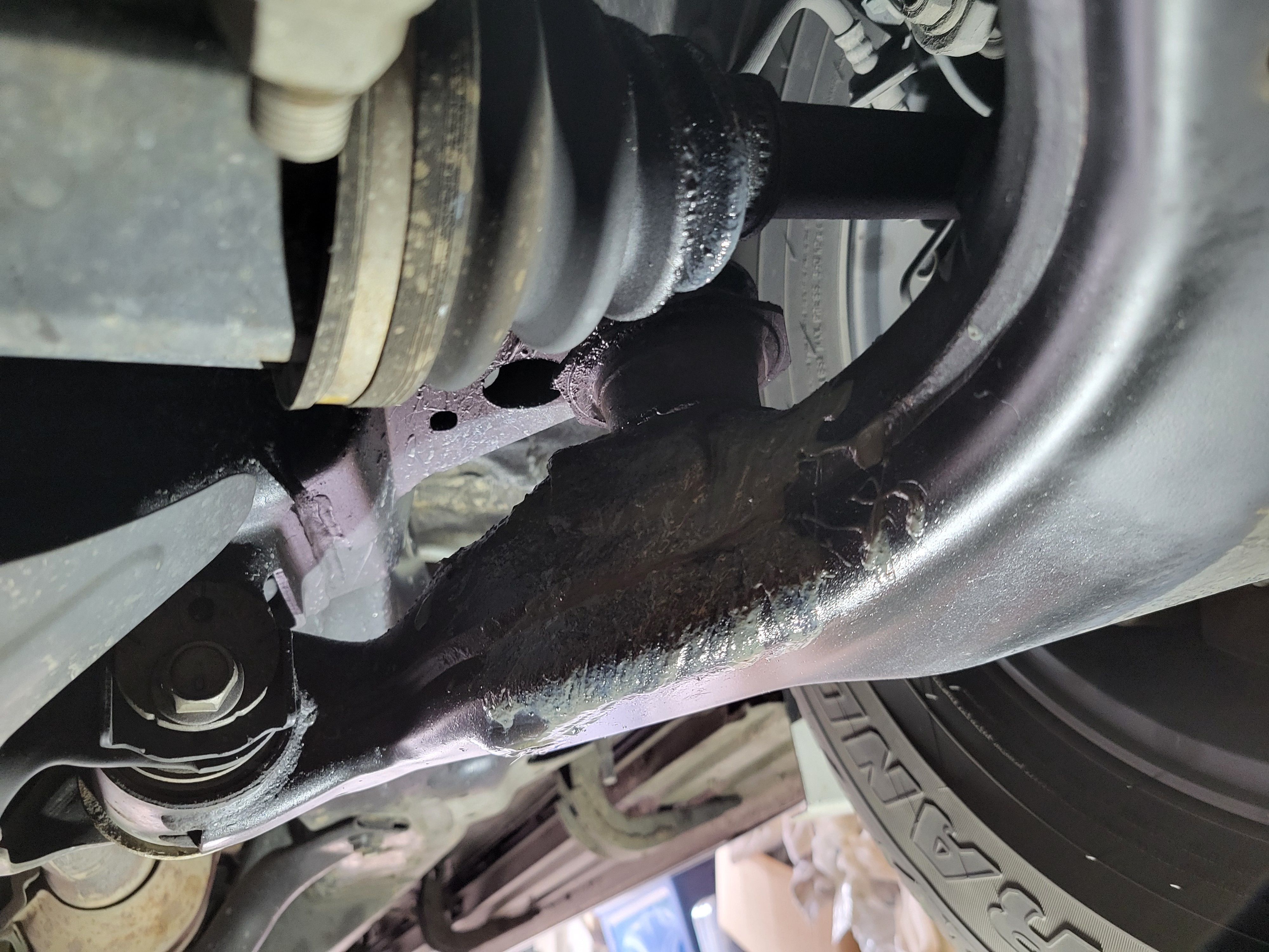
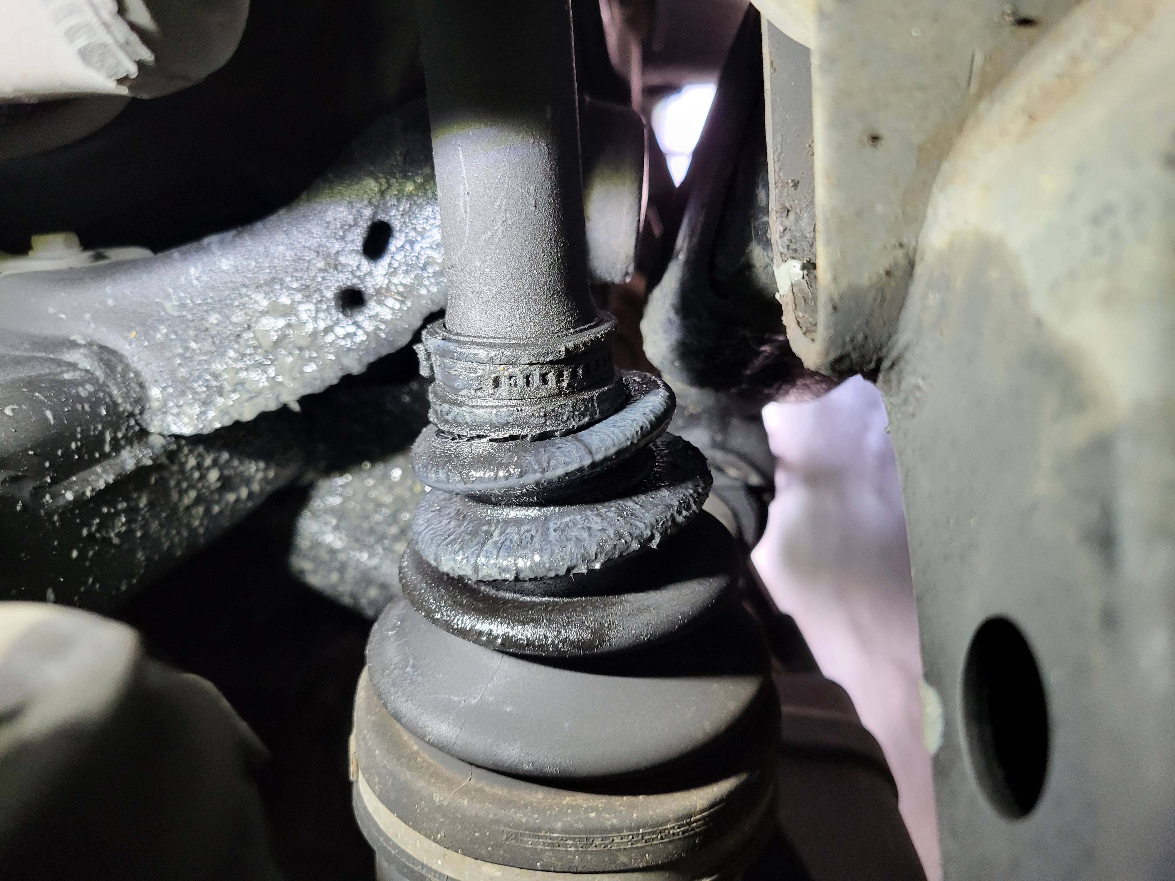
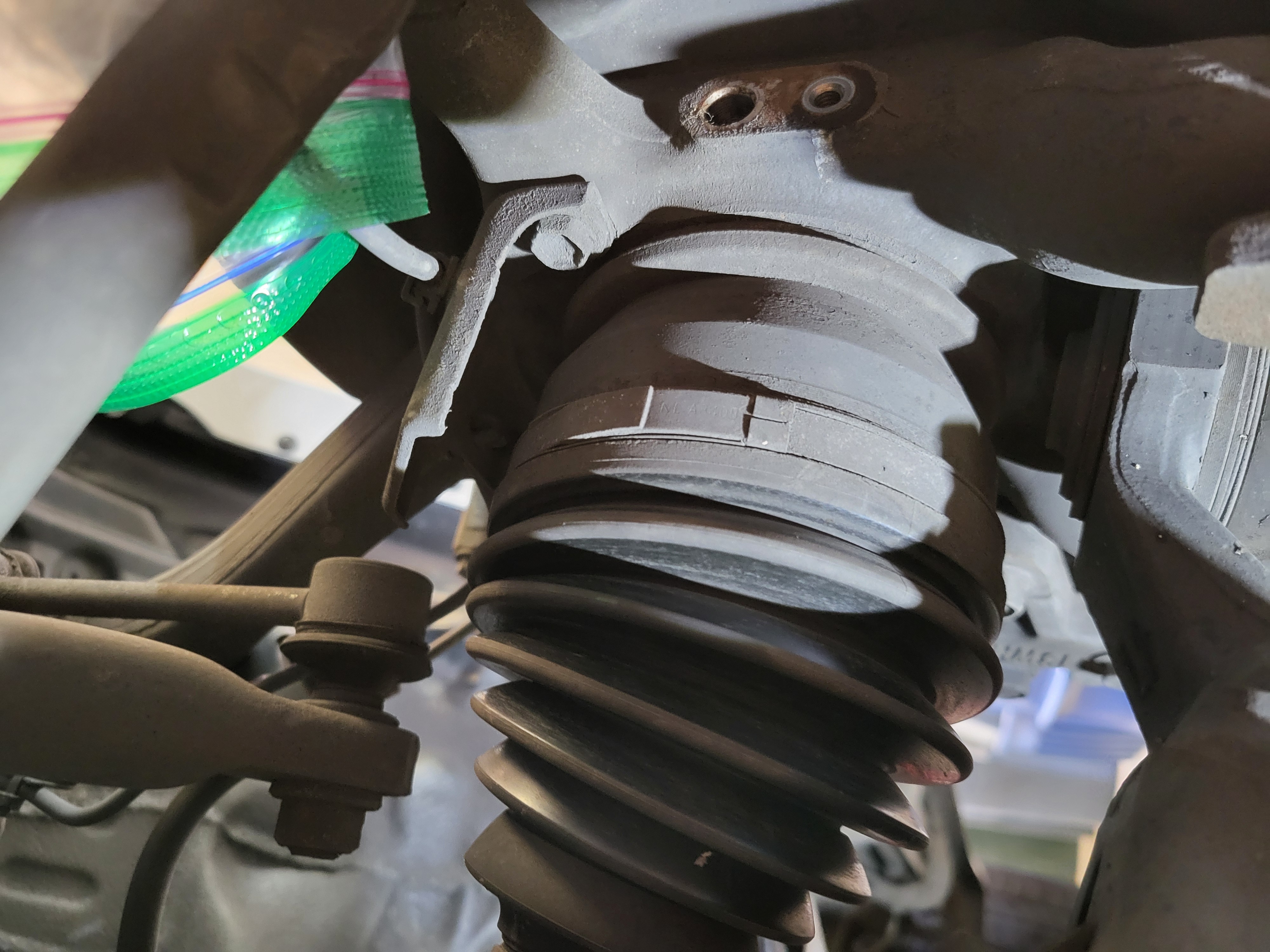
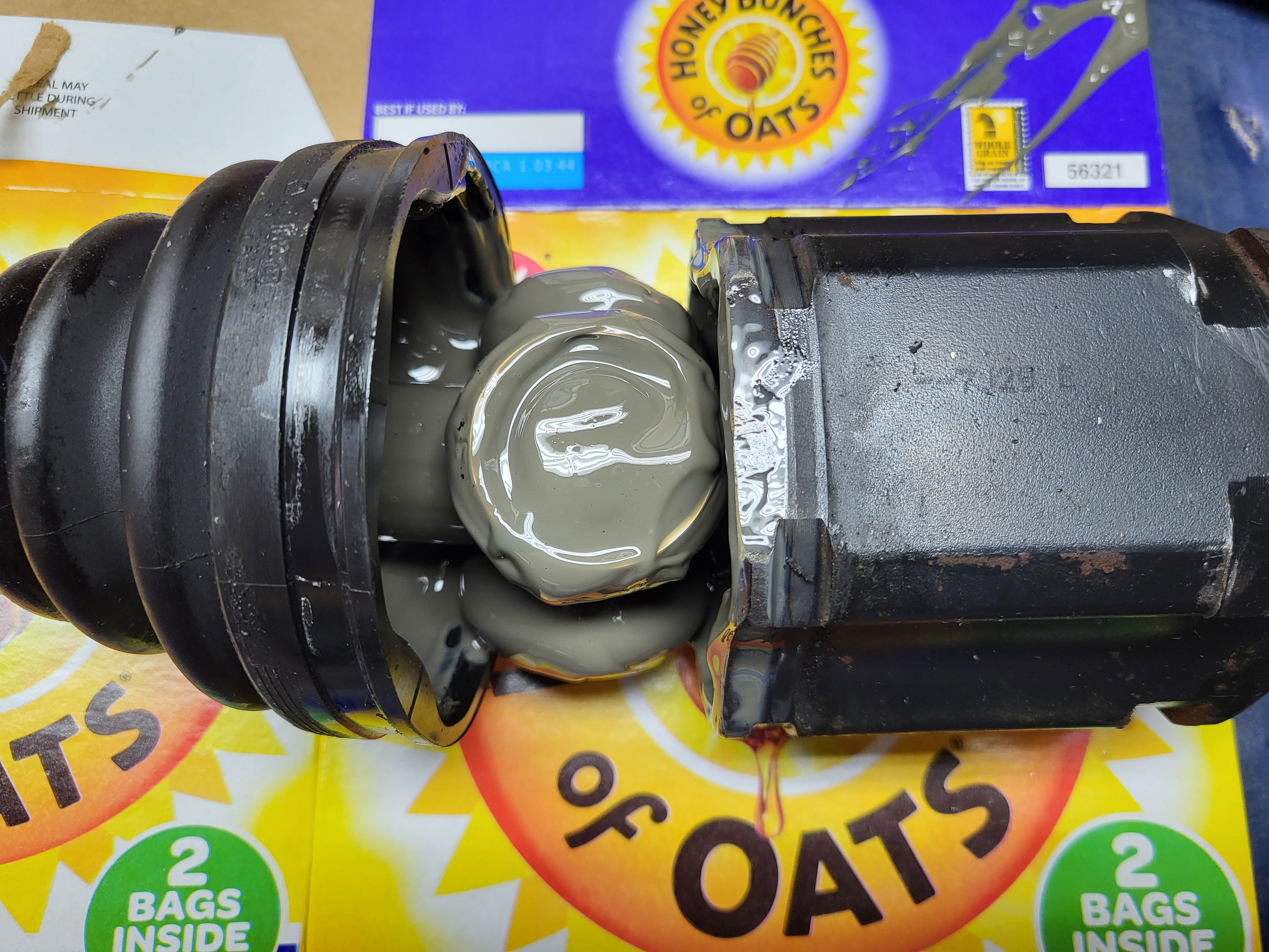
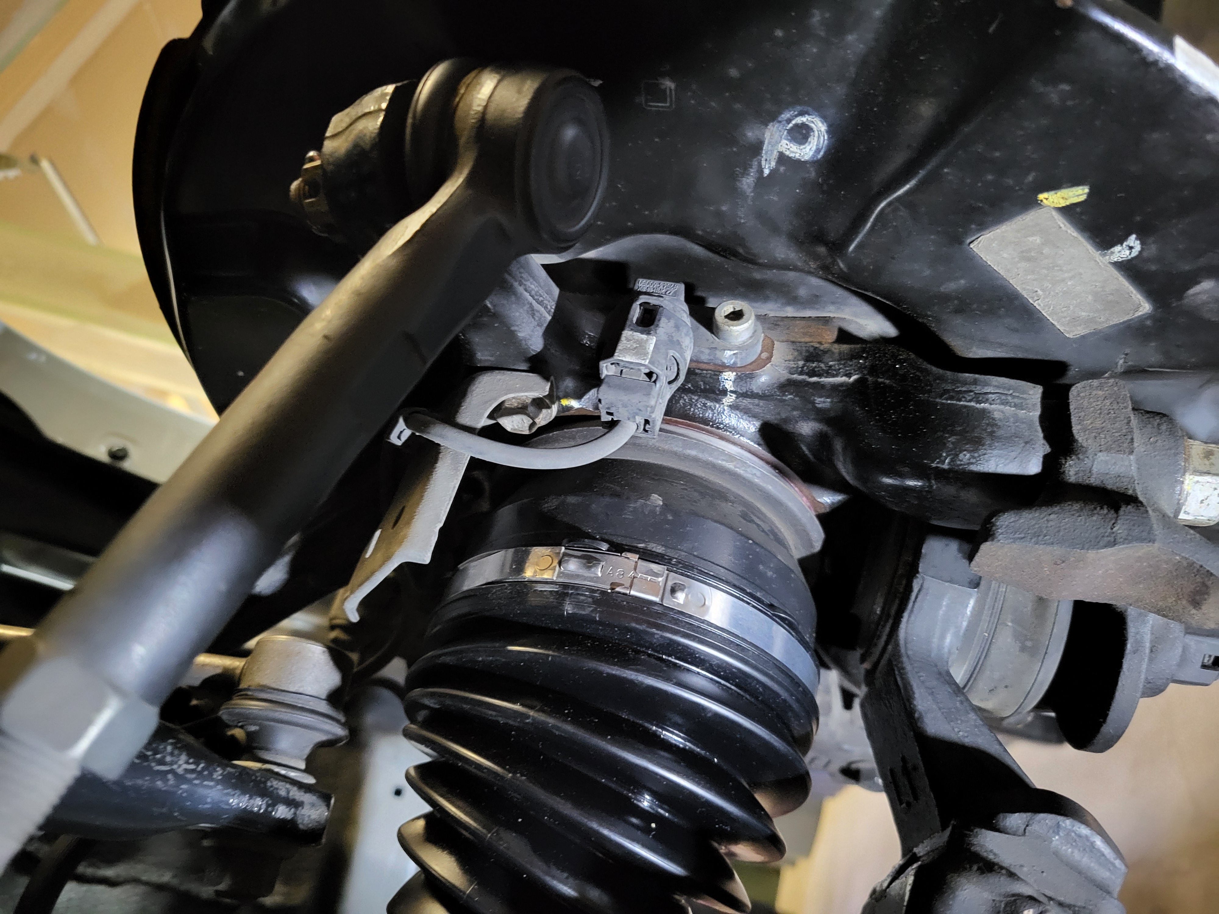
There are many reasons to reboot or replace the front CV axle on the GX470, in this case the inner drivers side boot had torn and was losing grease. The tear was relatively recent as the grease was semi-viscous and there were no other issues such as clicking or wheel shimmy.
Toyota/Lexus axles are high quality and rebooting them is preferred to replacing them with aftermarket axles from an autoparts store. However, if an axle does need to be replaced, replace it with a Toyota/Lexus axle or an axle rebuilt using Toyota parts from a reputable source such as CVJ Axles.
The following instructions adhere closely to the 2008 GX470 Repair Manual Volume 1 section "DS" with useful information gathered from others who are gracious enough to provide online videos or write-ups. Please follow these steps at your own risk, you are liable for any damage you may do to yourself or your vehicle.
The following videos and forum posts were helpful in putting these instructions together:
CV Axle Repacement
CV Axle Reboot
Note: this is not a GX470 axle, but the process is the same.
2005 Lexus GX470 Repair Manual (note the instructions and torque values in the 2005 repair manual are different than the 2008 repair manual used for these instructions)
Parts (to complete both axles)
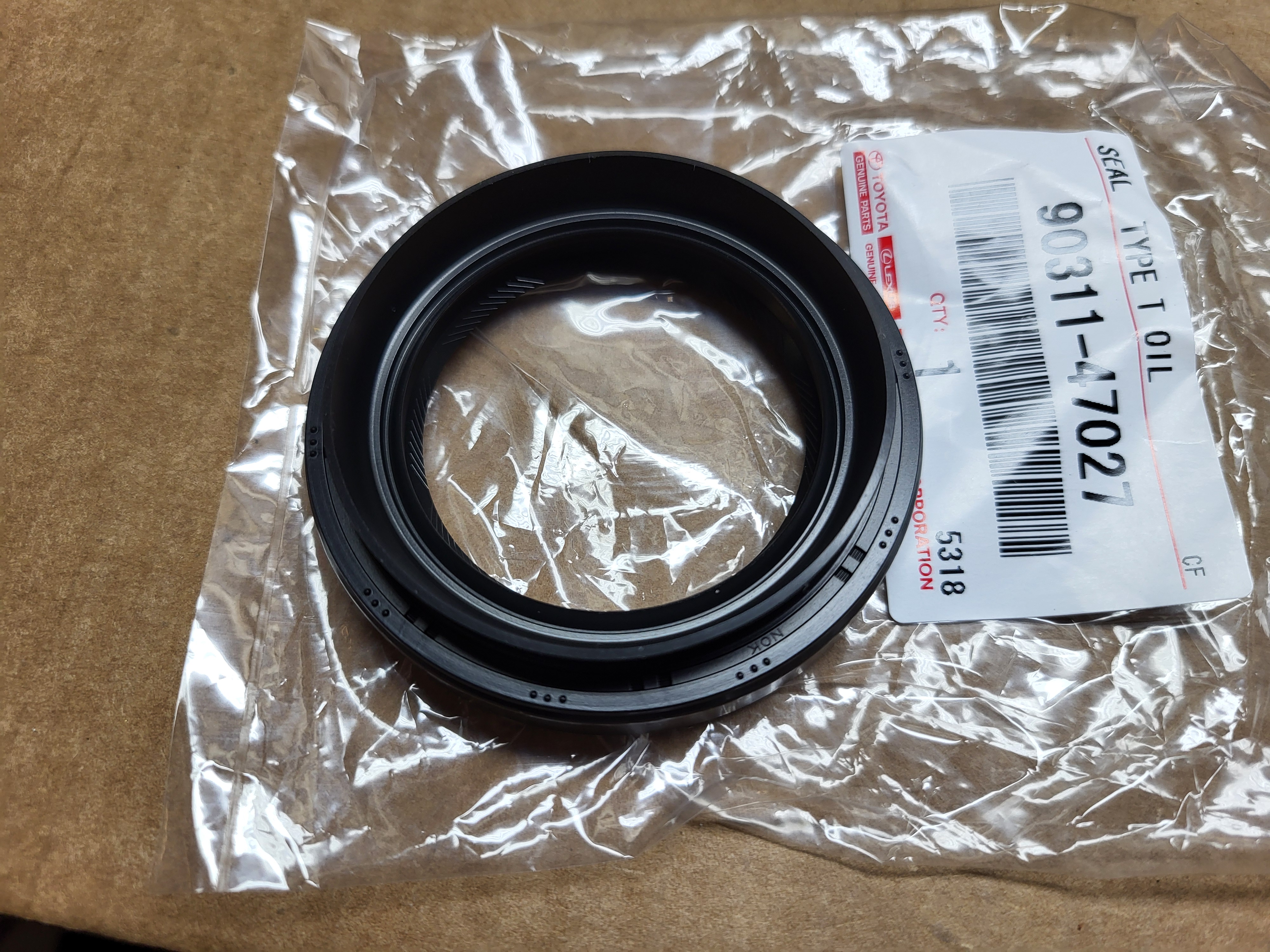
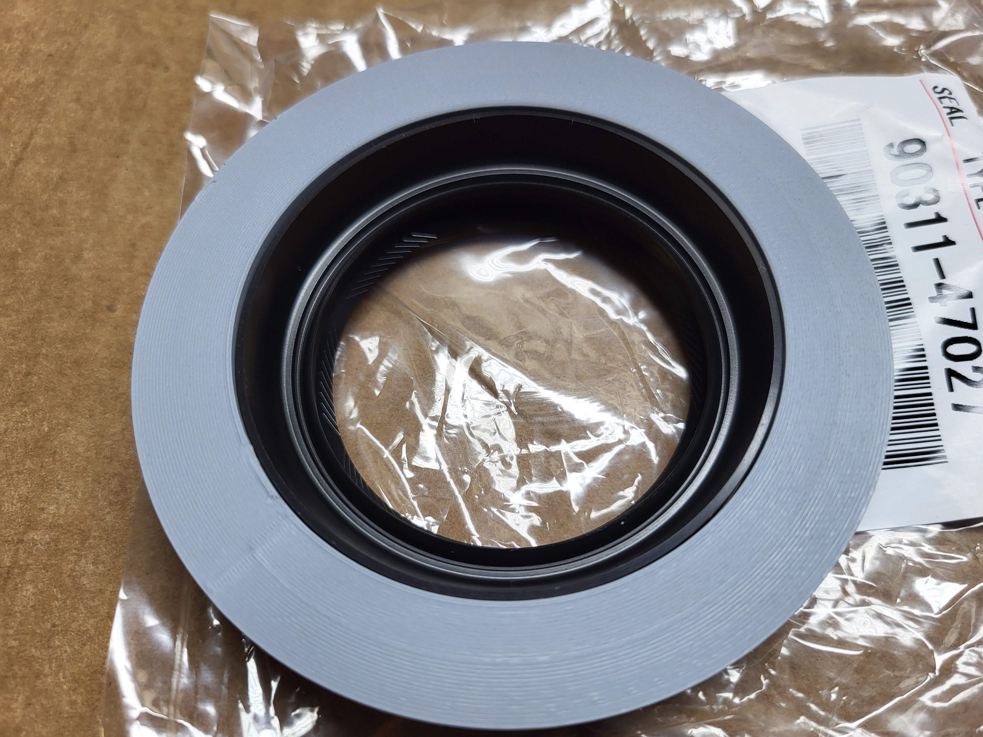
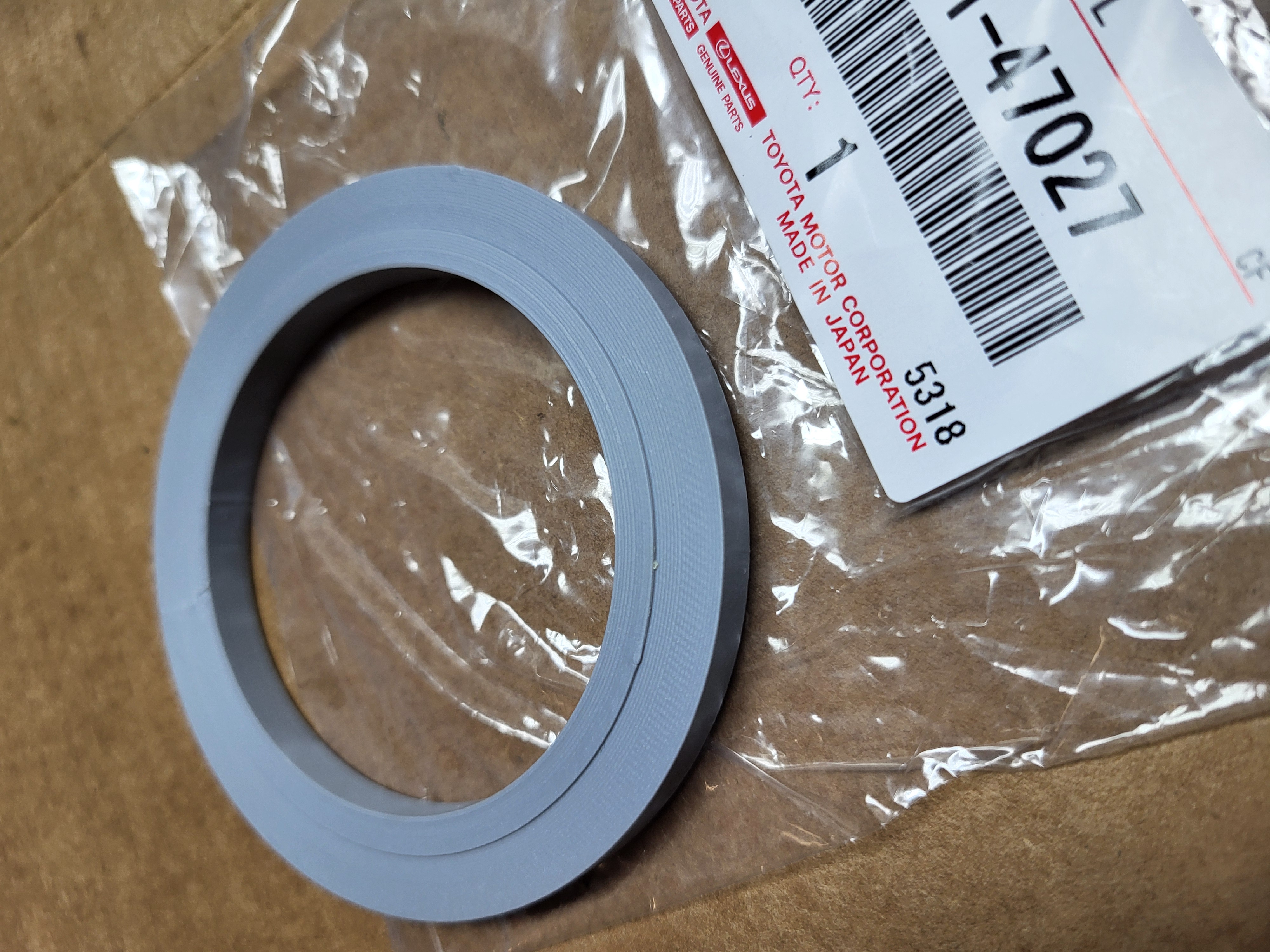
90311-47027 - Front Differential Axle Shaft Oil Seal (Drivers Side)
90311-47013 - Front Differential Axle Shaft Oil Seal (Passenger Side)
90316-70001 - Steering Knuckle Oil Seal (Need 2)
41336-35020* - Inboard CV Axle Dust Shield (Need 2)
90304-83002* - Outboard CV Axle Oil Seal Dust Shield (Need 2)
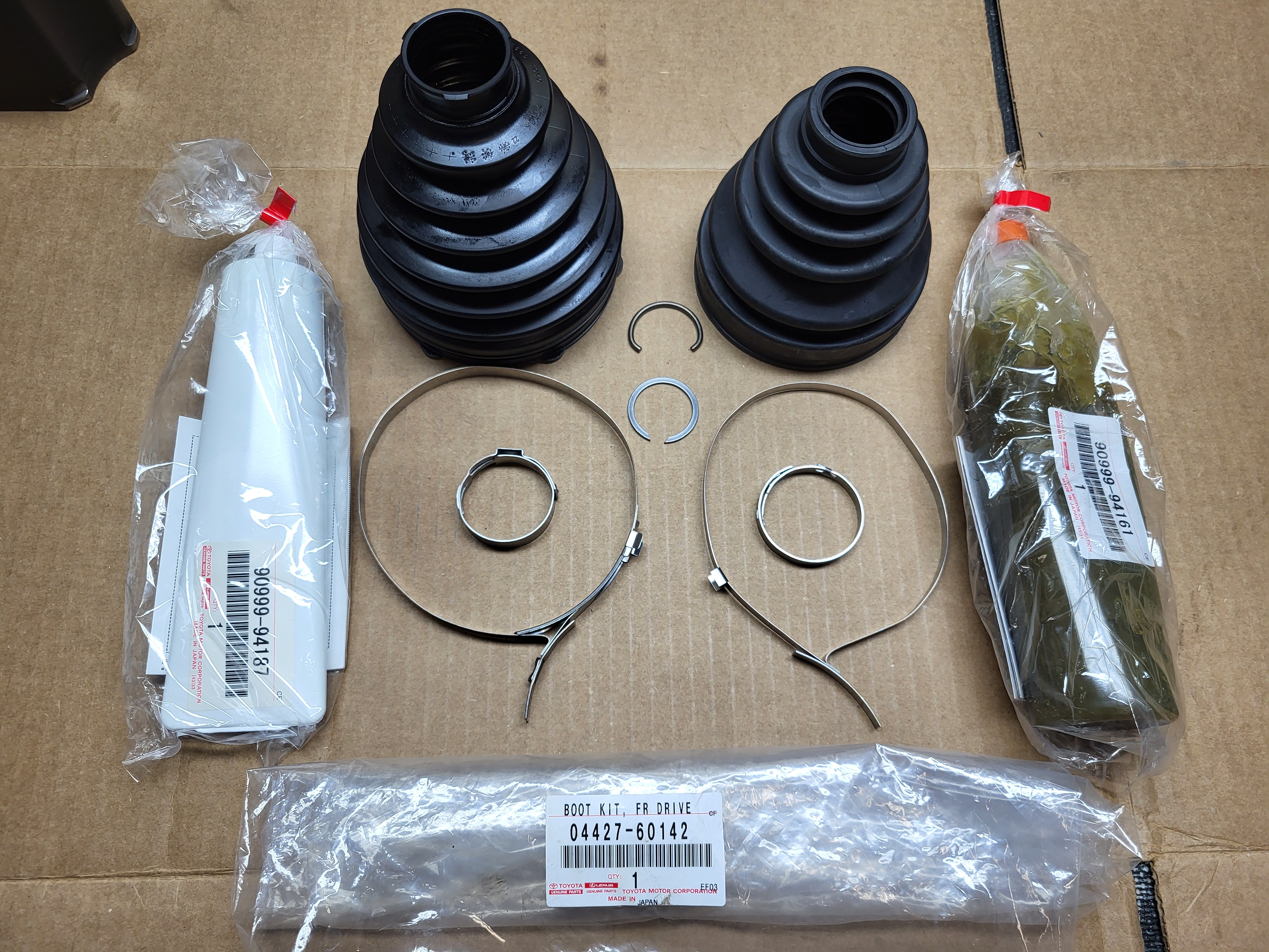
04427-60142 - Front Axle Shaft CV Boot Kit (Need 2) Kit includes inner and outer boot, inner and outer grease packs, (4) boot clamps, and (2) snap rings.
95381-04045 - Axle Hub Nut Cotter Pin (Need 2)
95381-03225 - Tie Rod Cotter Pin (Need 2)
90341-18060 - Front Differential Fill Plug (Optional - this replaces the internal 10mm hex plug with an external 14mm hex plug)
90341-24016 - Front Differential Drain Plug (Optional - this replaces the internal 10mm hex plug with an external 14mm hex plug)
12157-10010 - Front Differential Fill Plug Washer
90430-24003 - Front Differential Drain Plug Washer
75W-90 Gear Oil (2 Quarts)
*A lot of CV replacement instructions show the re-use of the oil seals and dust shields, however these are listed as "non-reusable parts" by the Lexus Repair Manual.
The oil seals should definately be replaced; if the dust shields on the CV axle are in good condition, they can likely be re-used.
Tools (lots of them, sorry no list)
CV Axle Removal
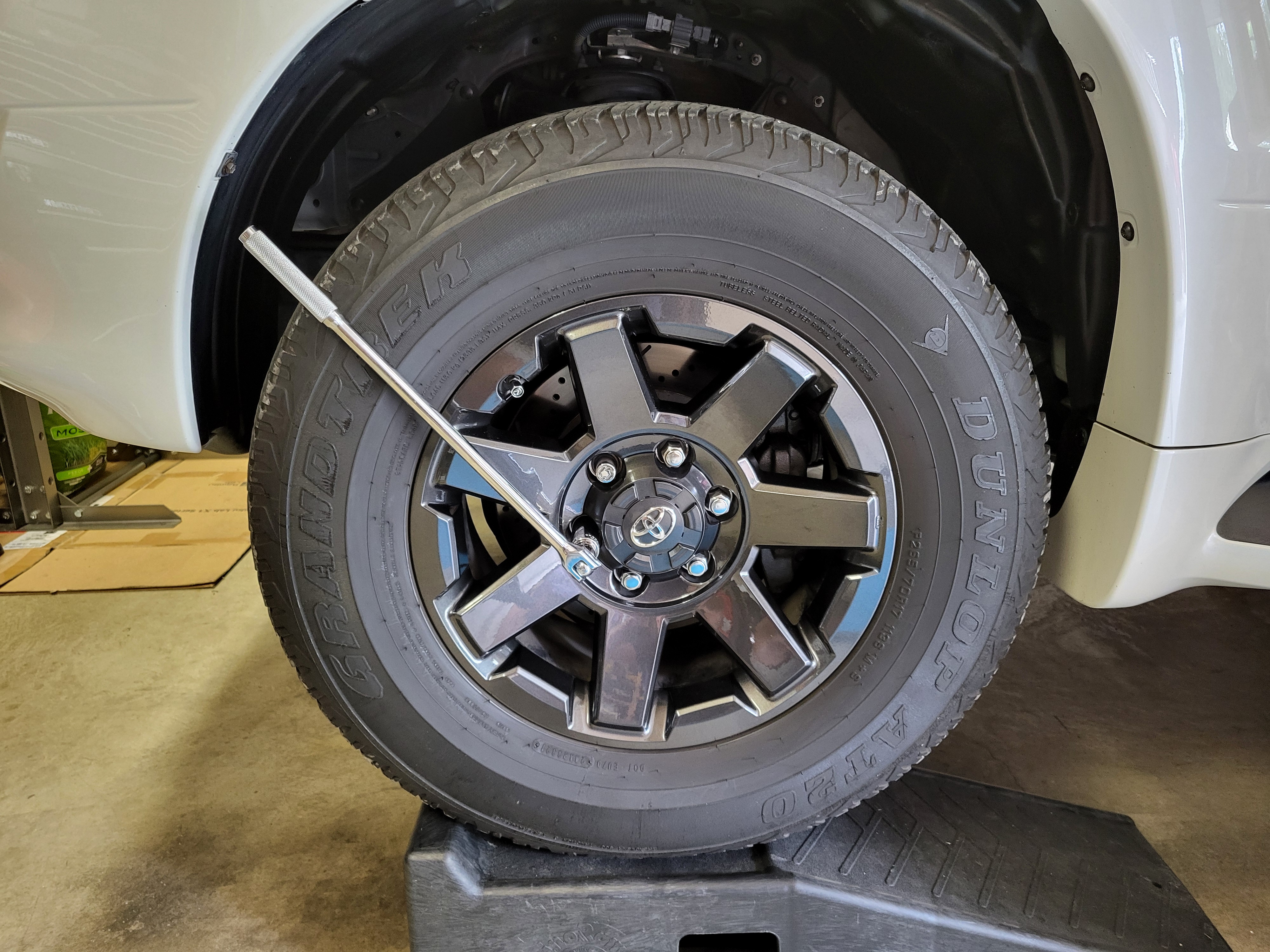
Step 1: Loosen wheel lug nuts
While the wheel is on the ground break free the wheel lug nuts ((5) 21mm nuts, (1) keyed nut). Do not remove the nuts, just break them free. Doing this after the wheel is off the ground is much more difficult as the wheel will want to spin when trying to loosen the lug nuts.
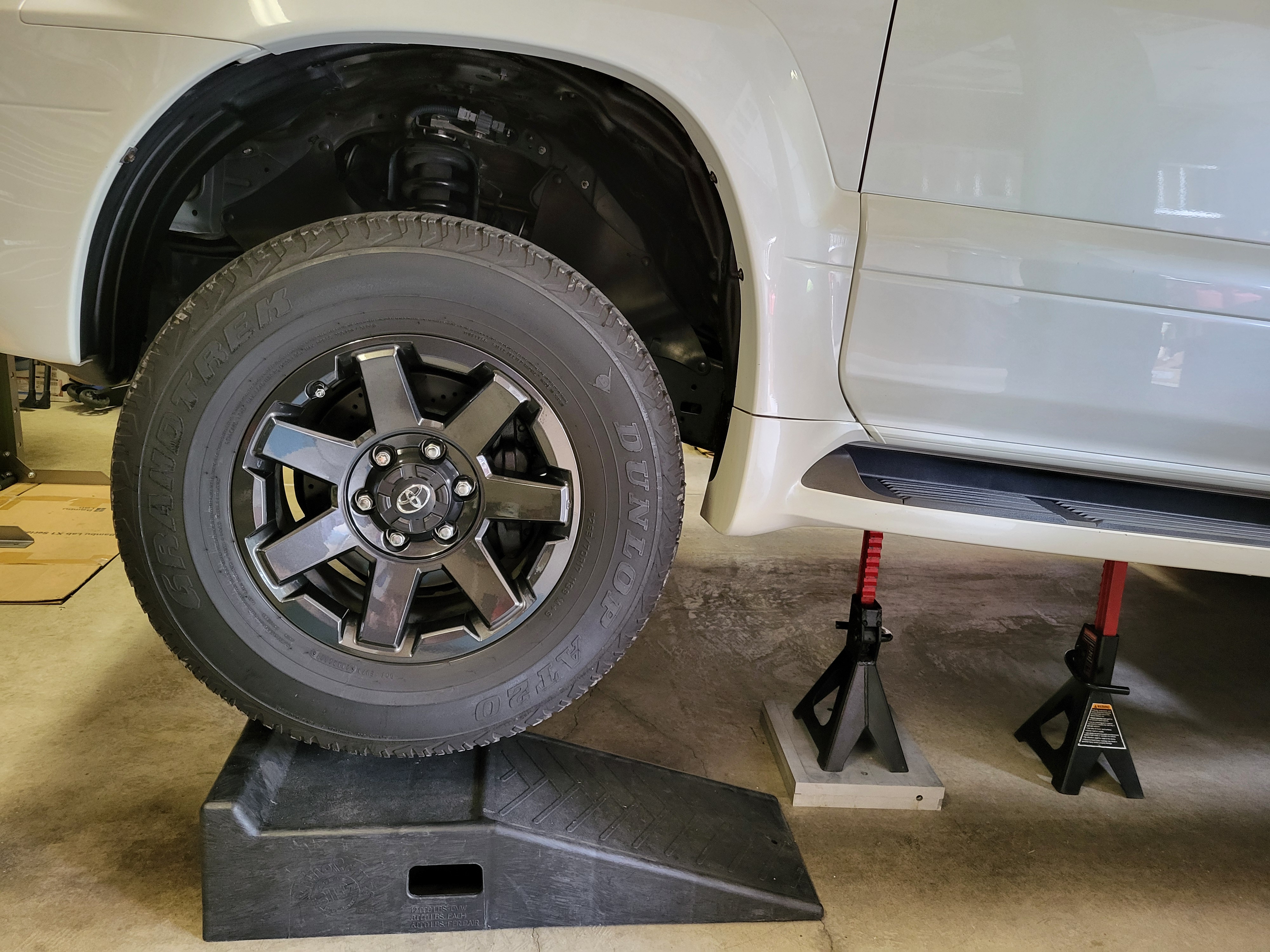
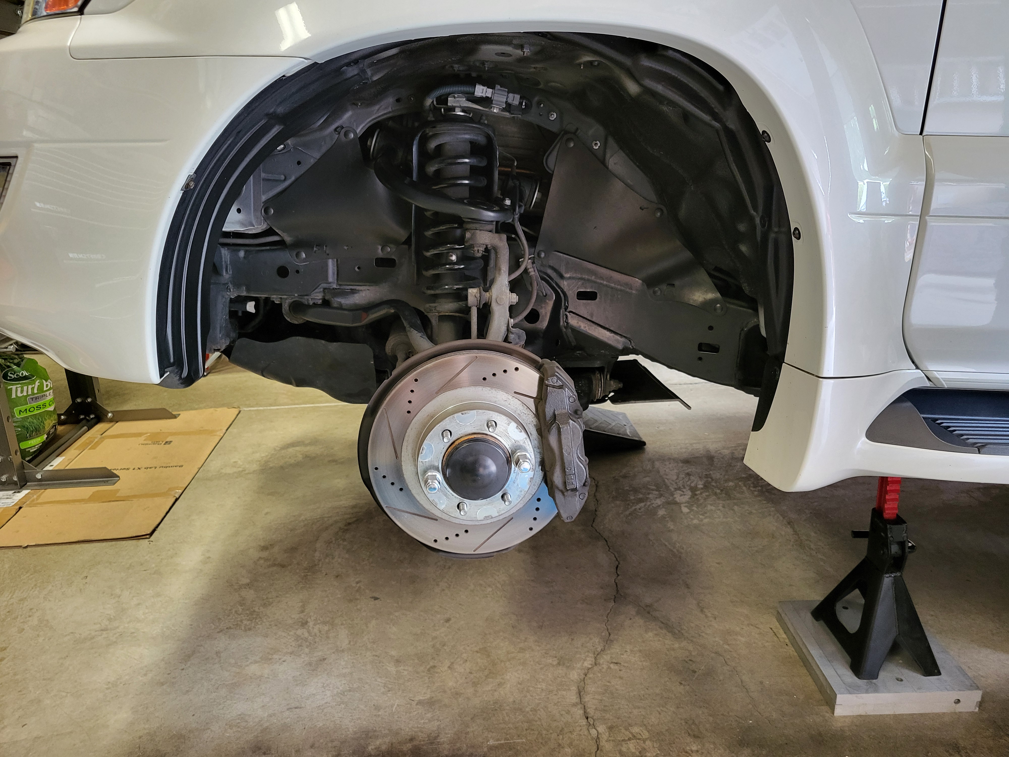
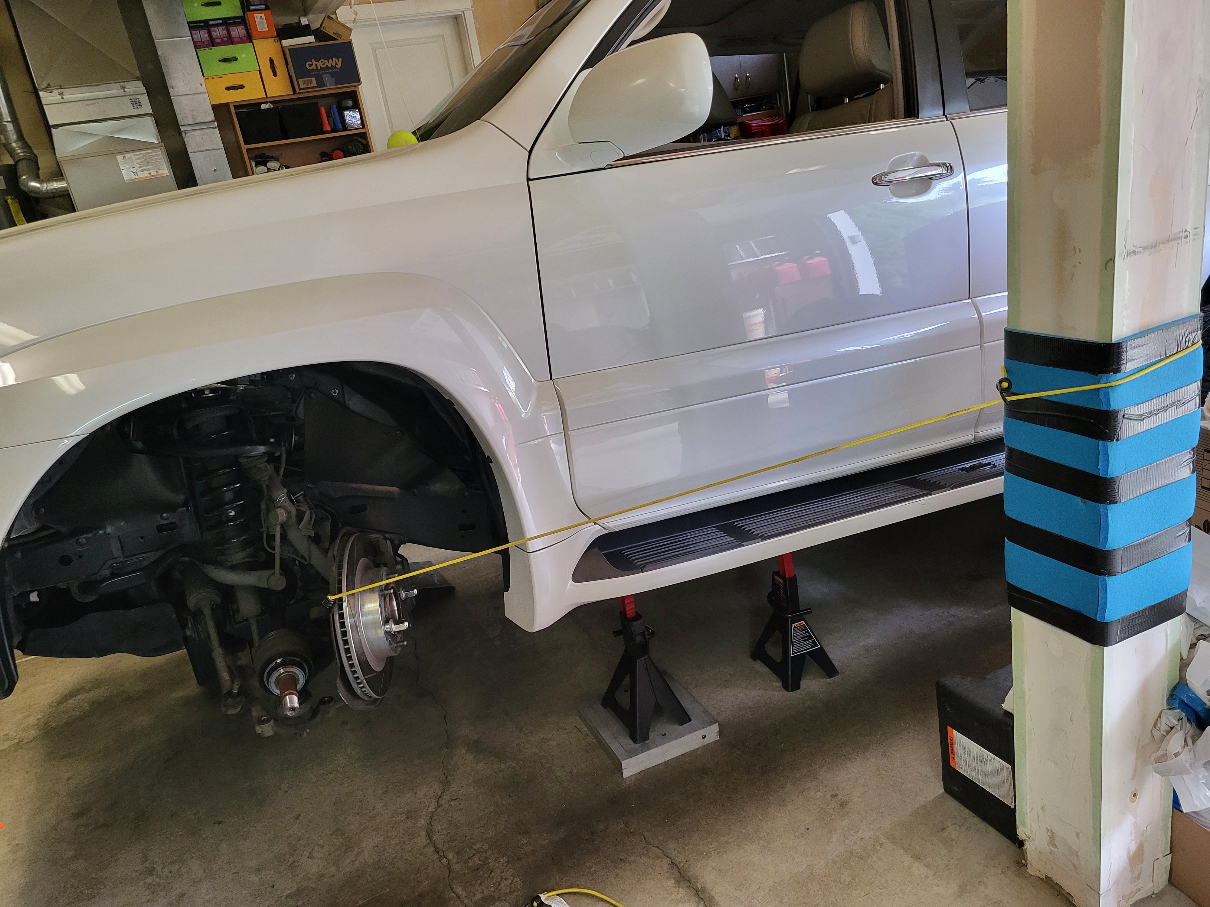
Step 2: Jack-up the vehicle for clearance
Place wheel chocks under the rear wheels, then jack-up the front of the vehicle to provide clearance to perform the axle work. A substantial amount of work will be done from underneath the vehicle, so getting it as high as your equipment allows makes the job easier. However, you really only need to get it high enough to get the wheel off the ground.
Step 3: Remove the front wheel
Remove the loosened lug nuts and pull the wheel off the vehicle. Reinstall a couple of lug nuts to secure the brake rotor.
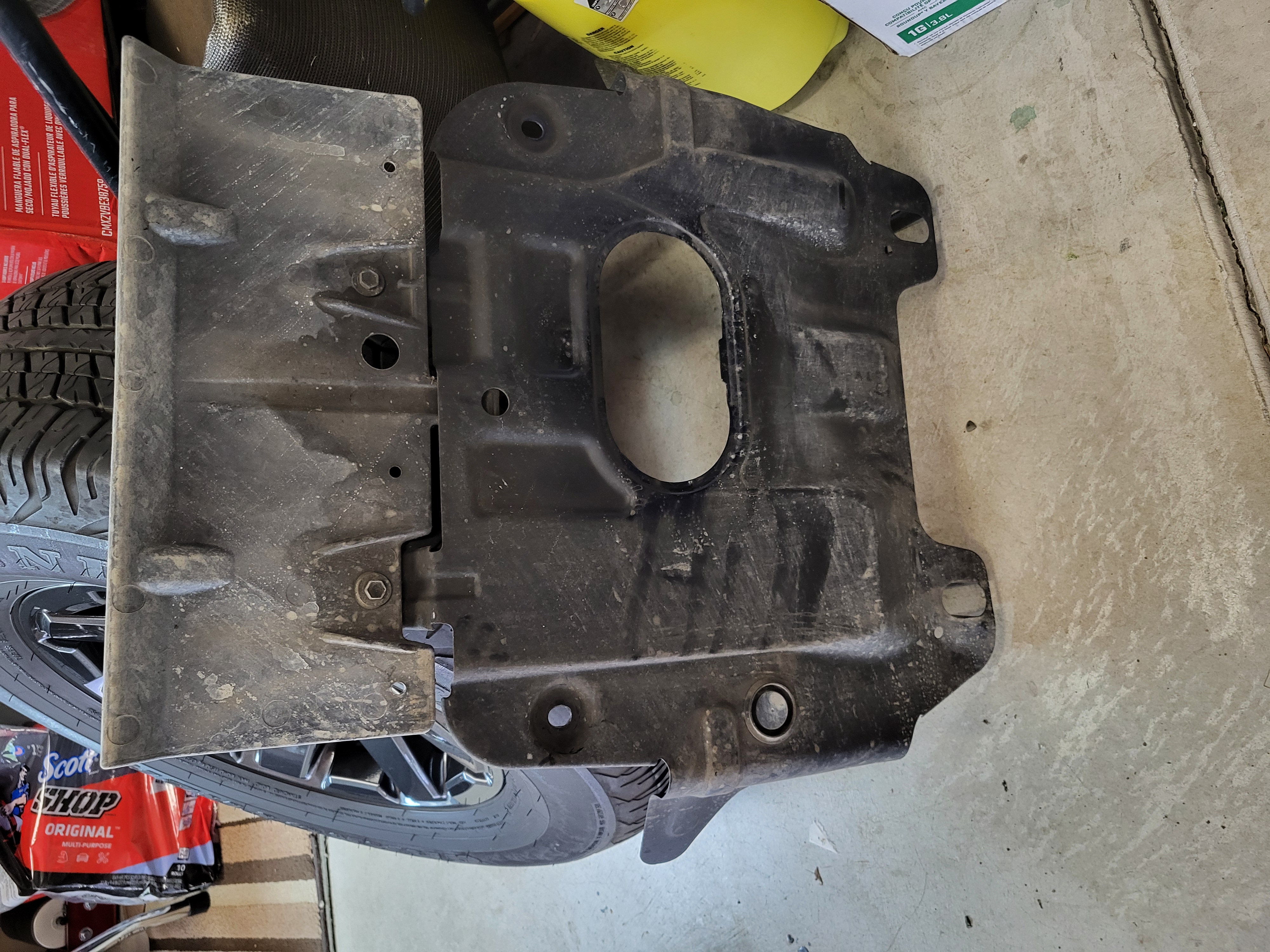
Step 4: Remove the skid plate
Remove the skid pate that is located under the front differential ((4) 12mm bolts with 3" extension).
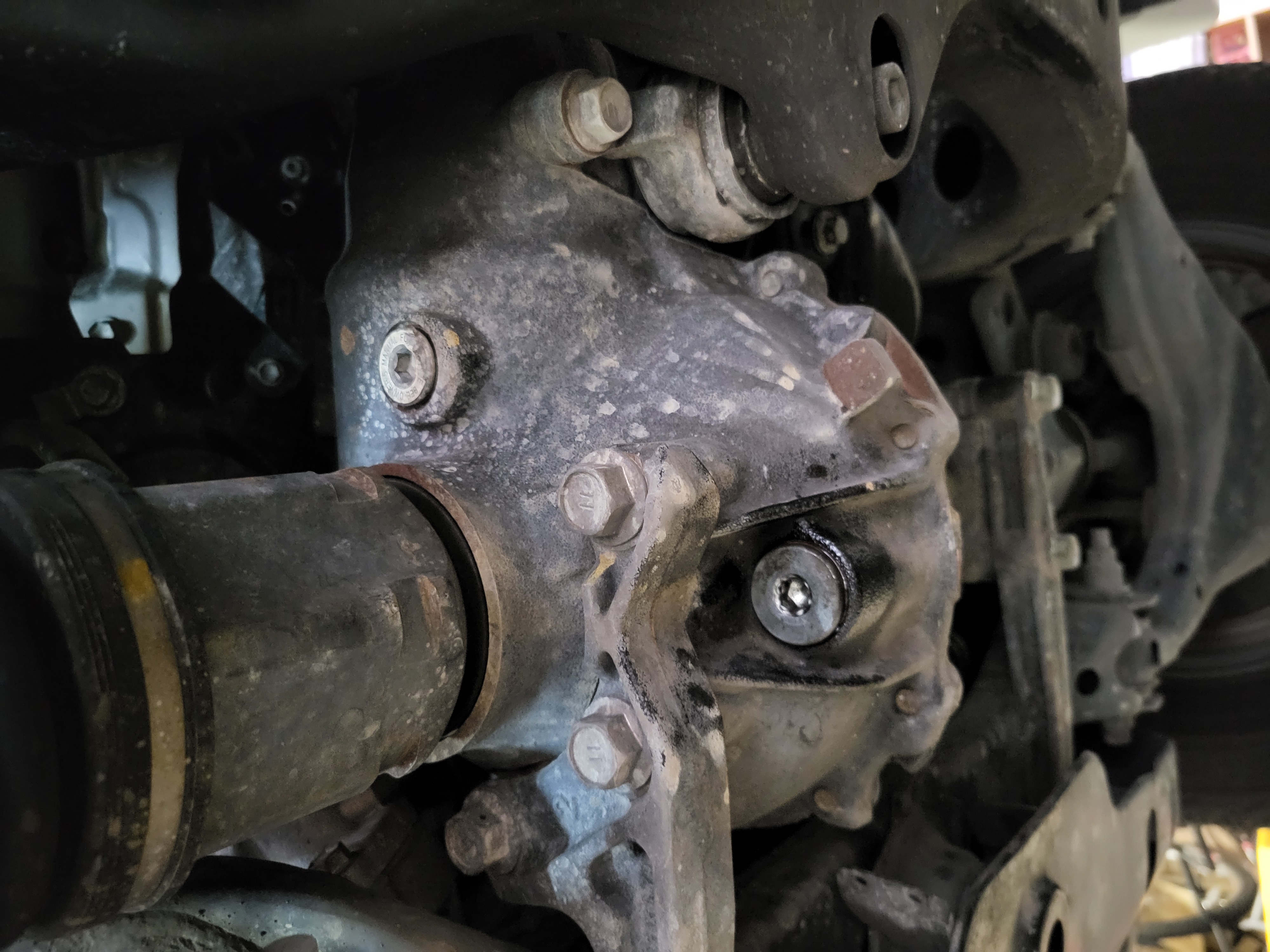
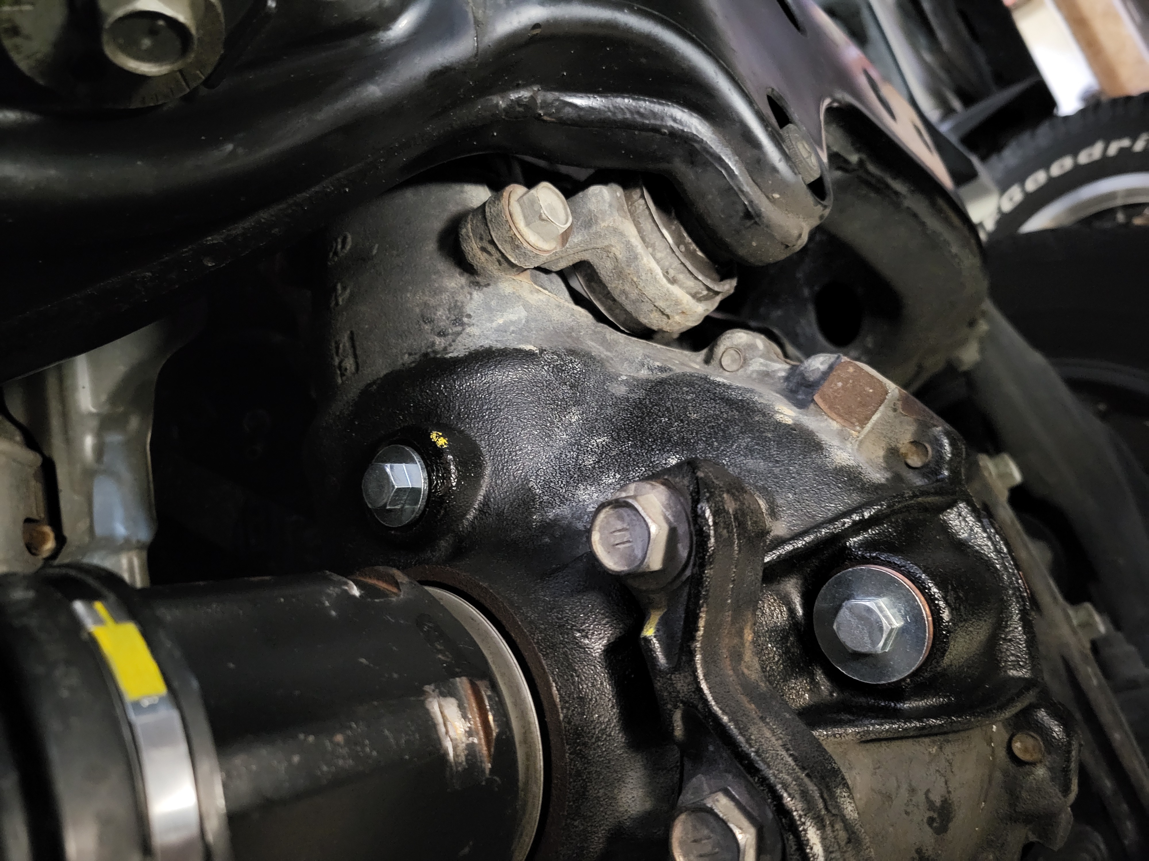
Step 5: Drain the front differential
Loosen the fill bolt to ensure it can be removed, then remove the drain bolt to drain the front differential ((2) 10mm recessed hex bolts). Once drained, reinstall the drain bolt to prevent leakage (it will be drained again when the vehicle is level and then installed permanently).
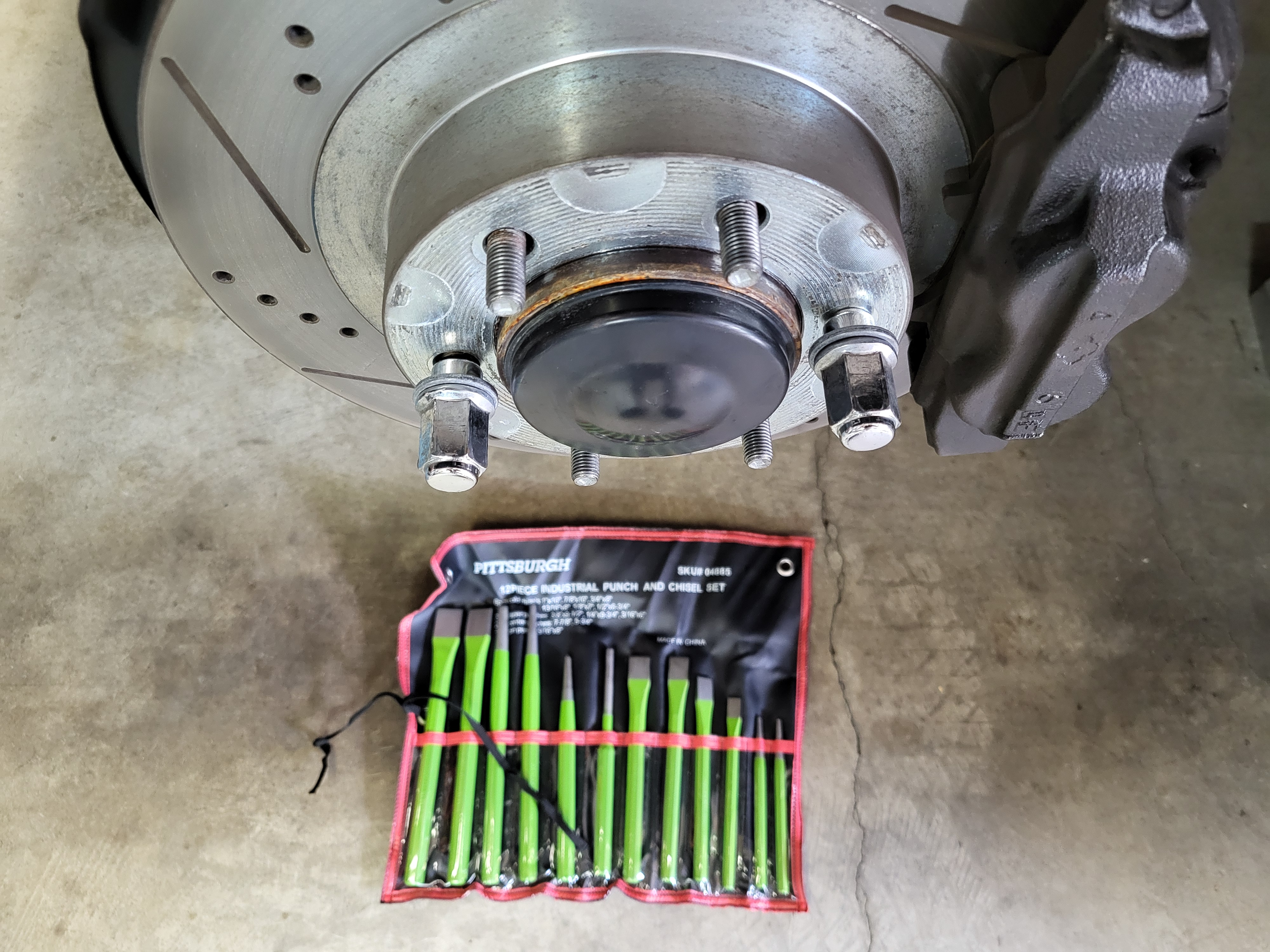
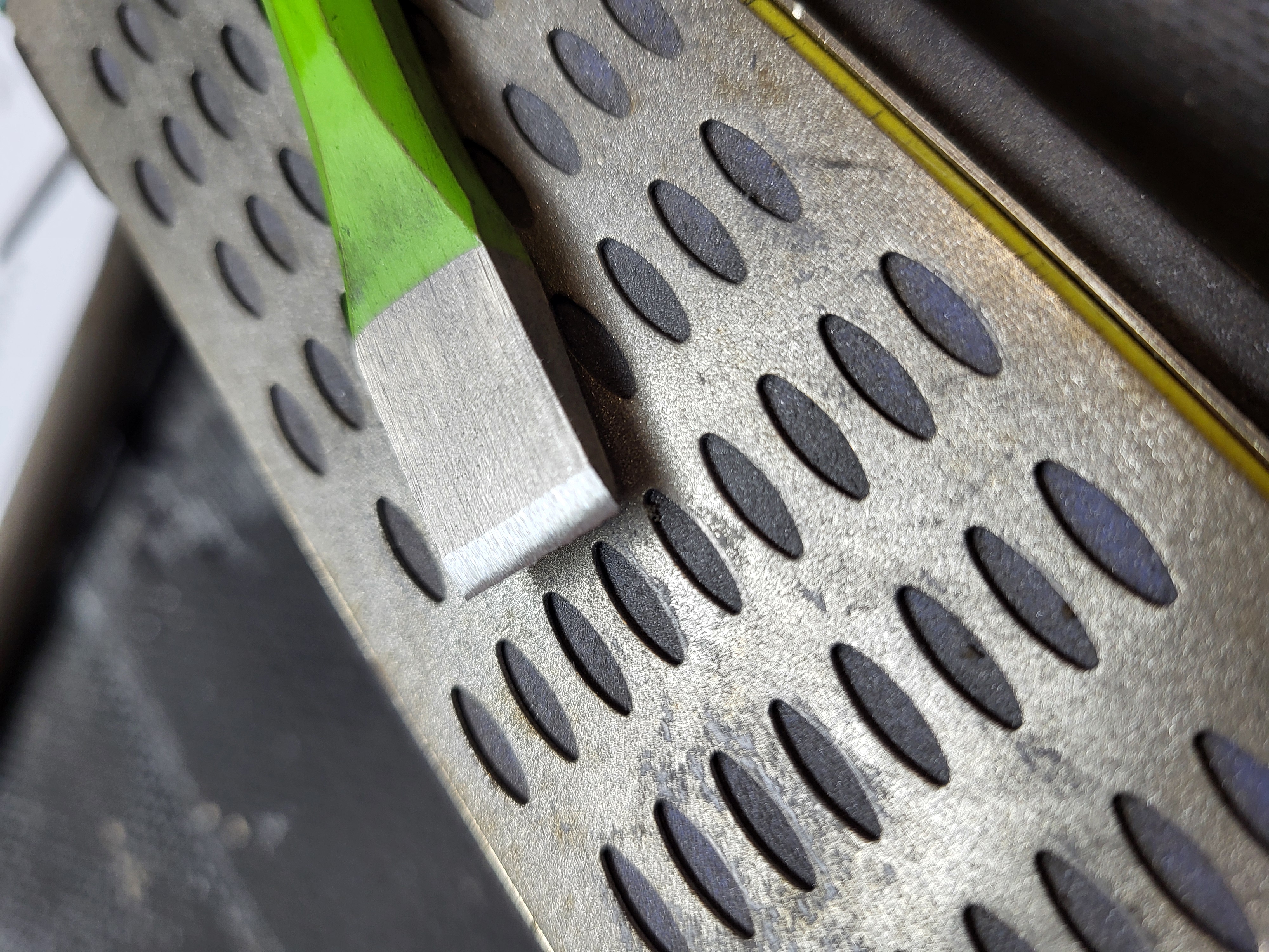
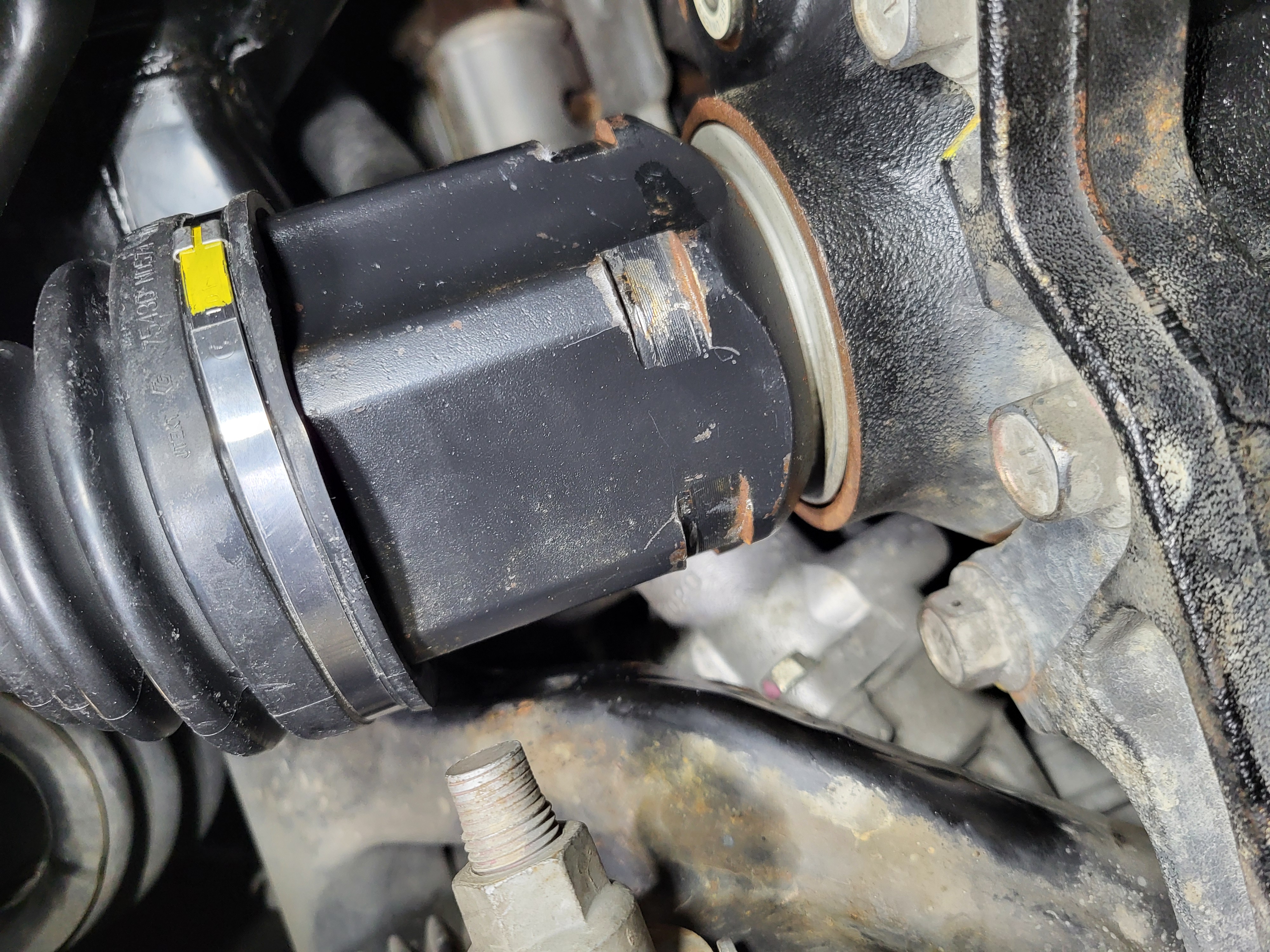
Step 6: Remove the axle dust cap
Using a cold chisel set, tap on the gap between the dust cap and the steering knuckle to gentle open the gap until it can be popped off with a small pry bar. Switch chisel sizes and rotate the rotor as necessary to work the dust cap gap open. Note: The chisel may need to be sharpened to get into the small gap and a 16oz hammer works better than a lighter one.
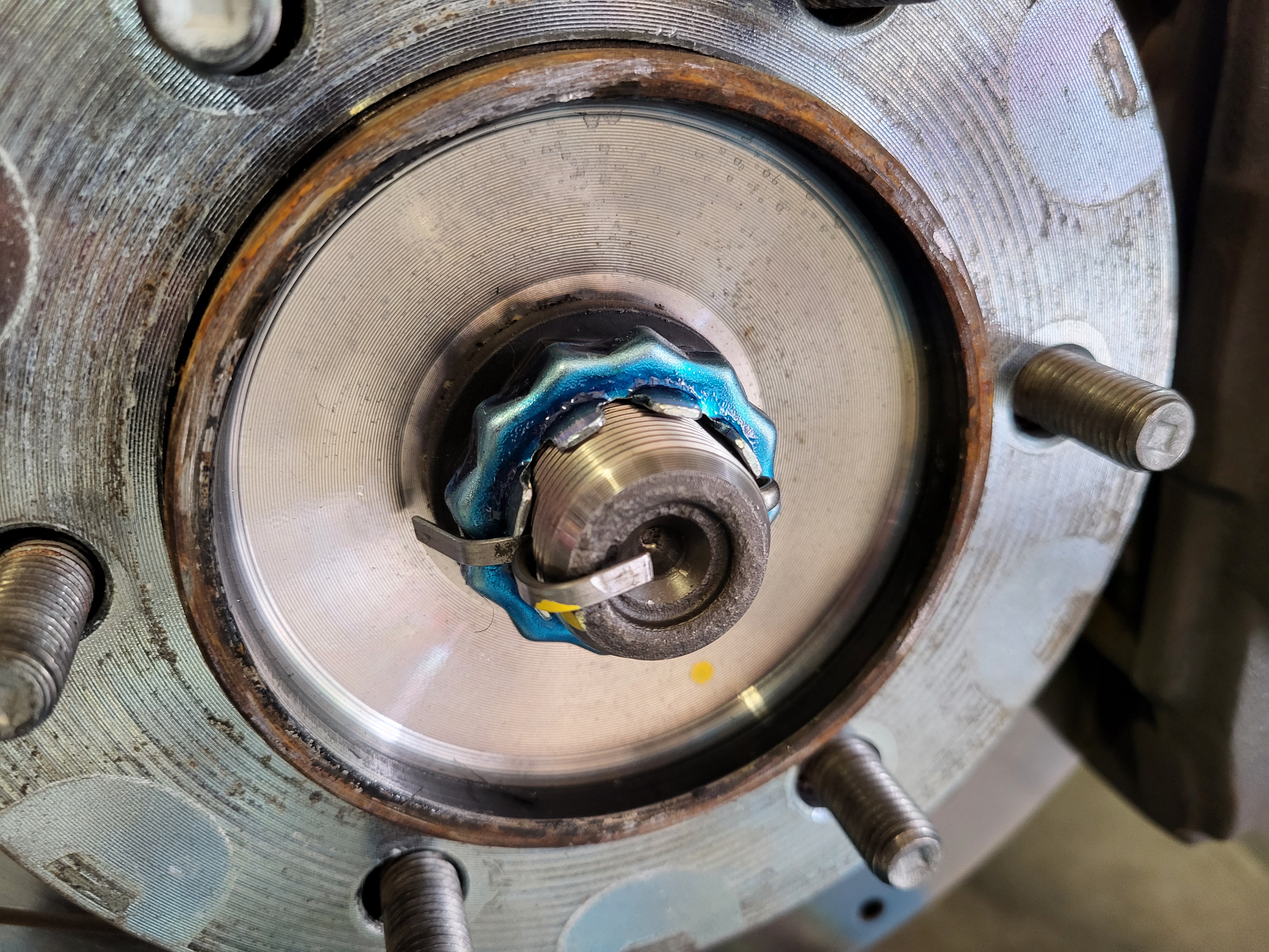
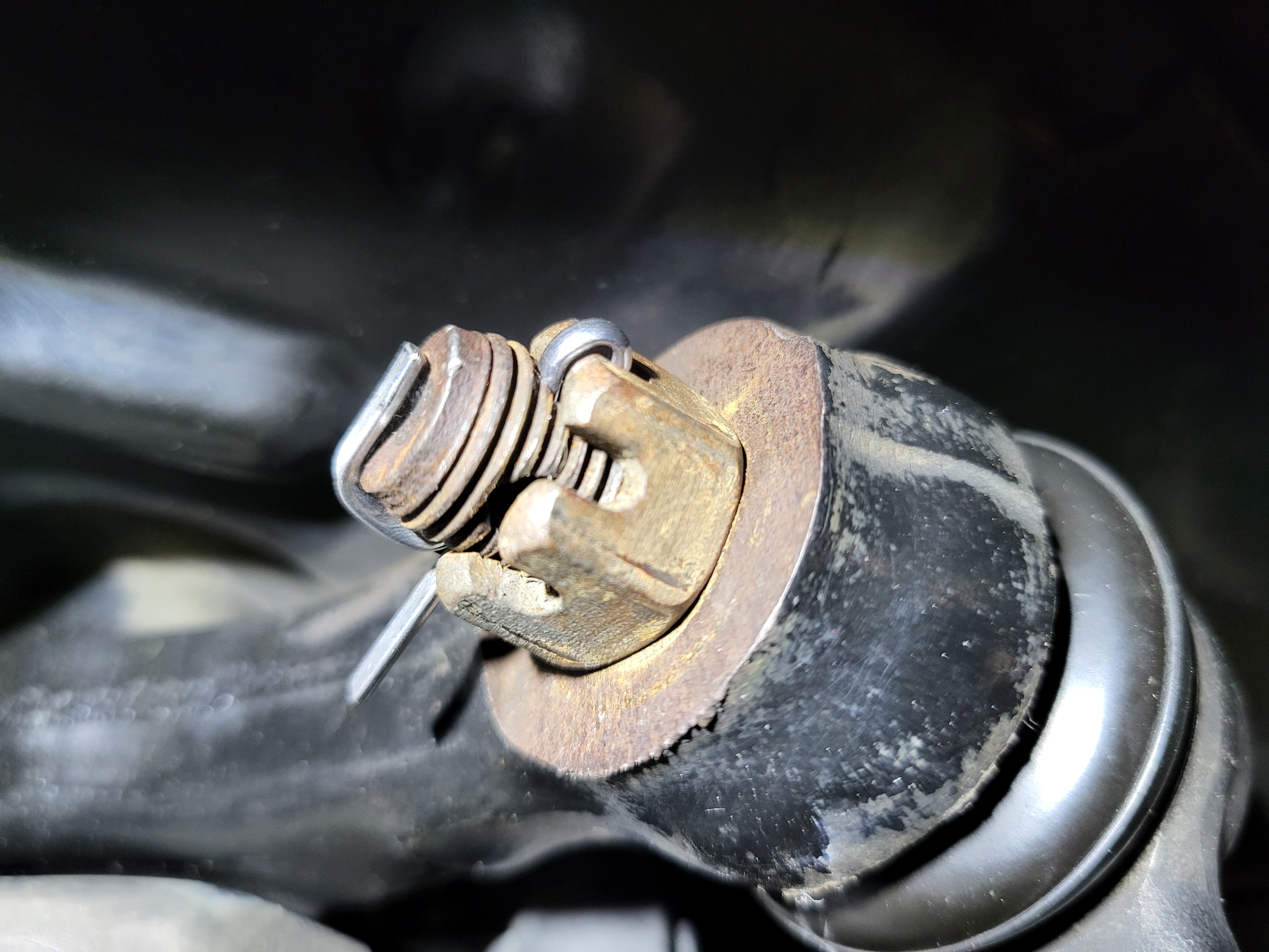
Step 7: Remove the cotter pin and locking/adjustment cap
Remove the cotter pin with pliers and then remove the locking cap.
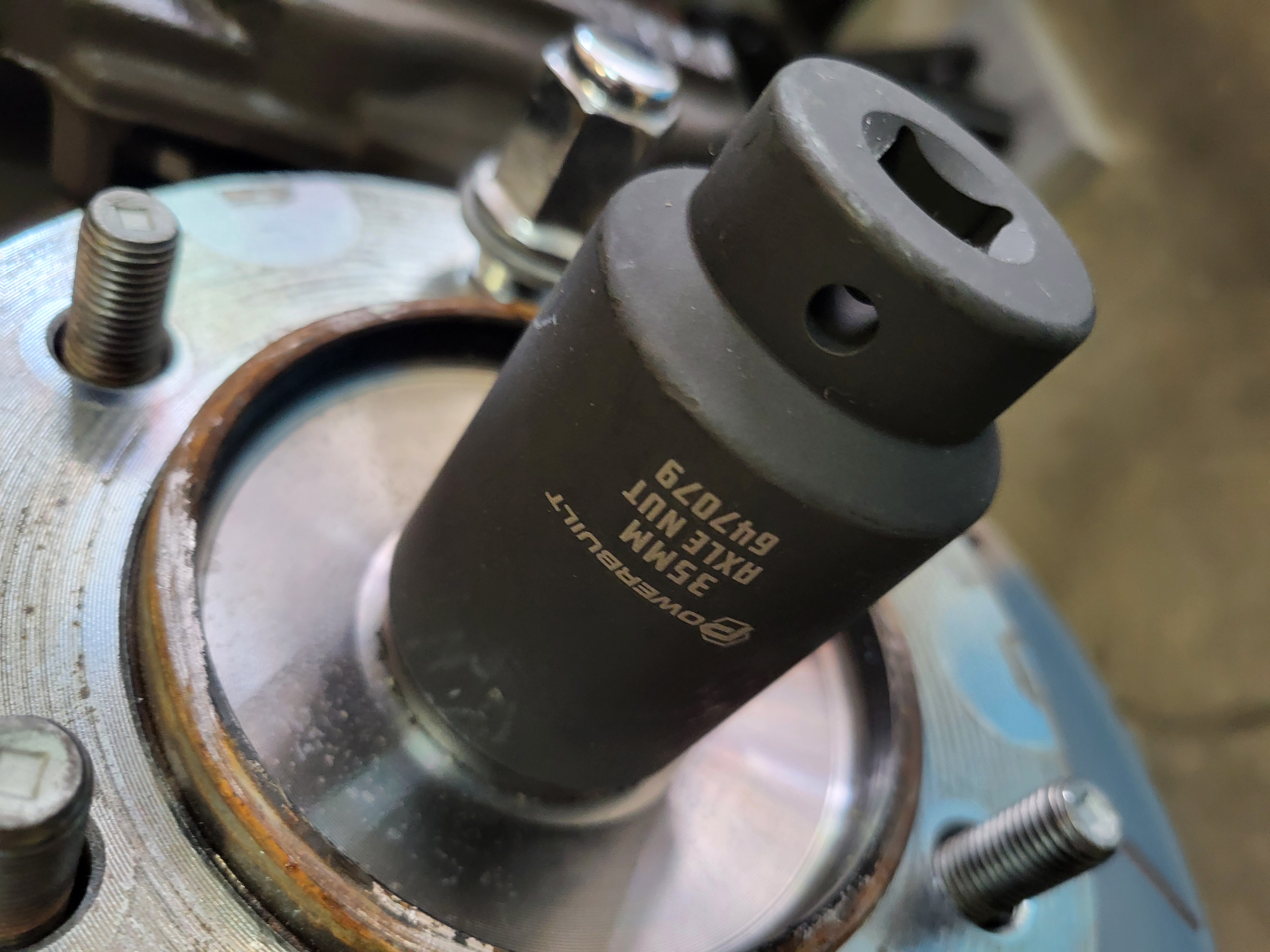
Step 8: Remove the axle nut
Remove the 35mm axle nut. This nut is installed with high torque, an impact gun may be required, or if you have a helper they can step on the brakes to prevent rotation while the nut is removed with a breaker bar. Another option is to put the wheel back on (with the wheel center cap off) then raise your floor jack under the wheel. Not enough to lift the vehicle from the jack stands, but enough to prevent the wheel from rotating as the nut is removed.
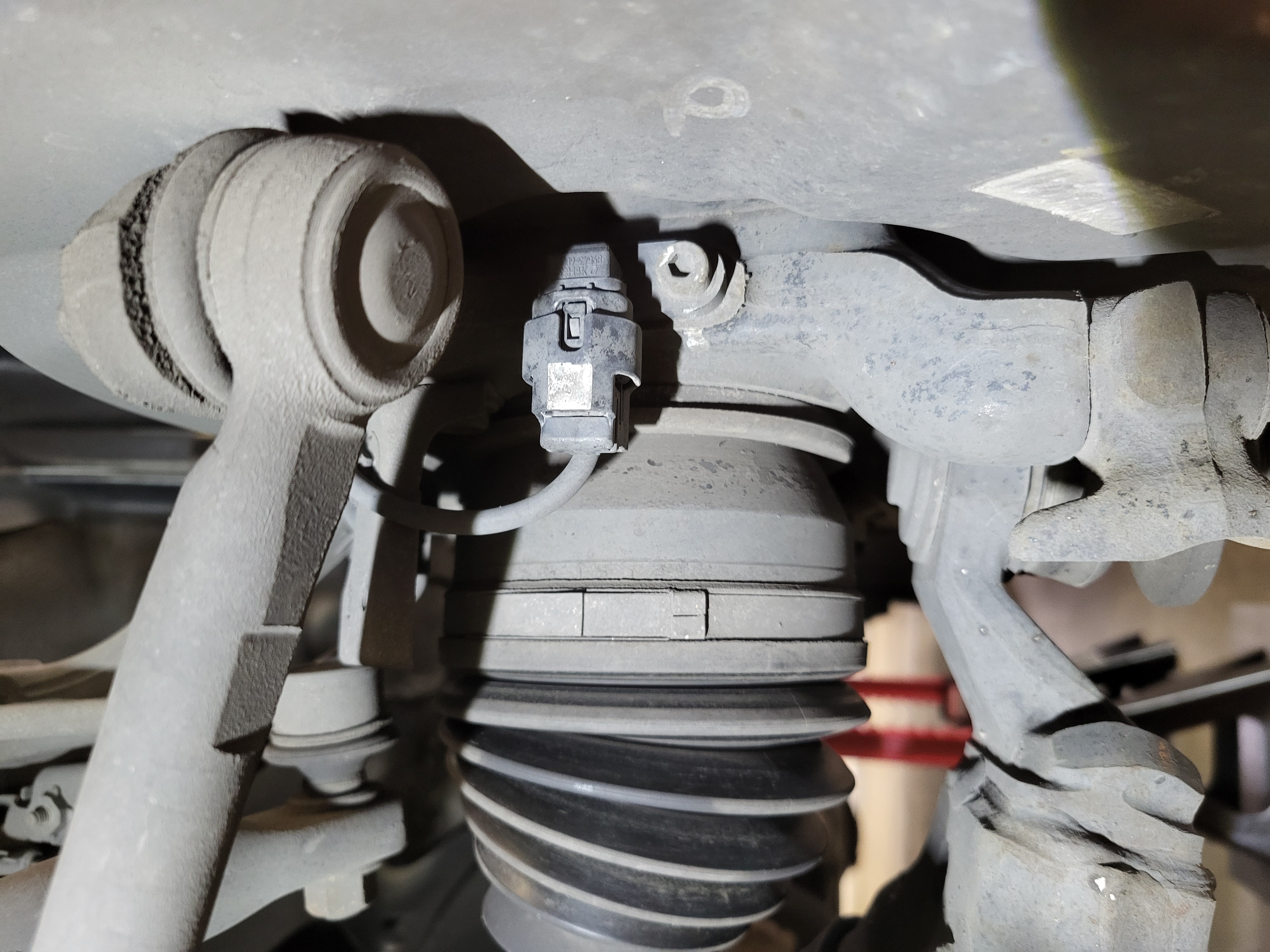
Step 9: Remove the front speed sensor
Remove the 5mm internal hex bolt securing the sensor to the steering knuckle. Then remove the speed sensor mounting bracket from the steering knuckle (12mm bolt). This may not be necessary, but it is in the repair manual. The sensor can be protected in a sandwich bag, and the assembly can be baling-wired to the upper part of the steering knuckle.
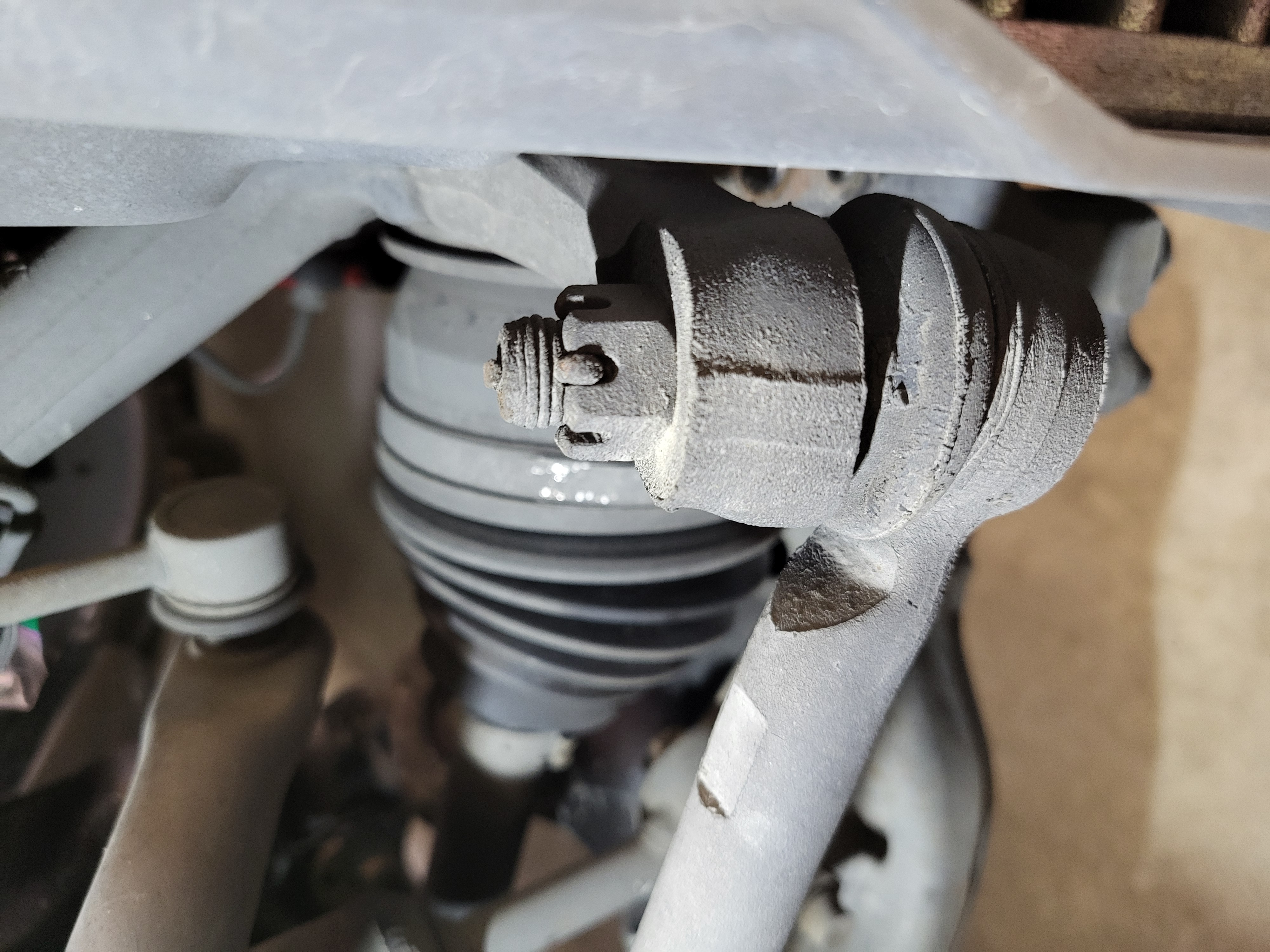
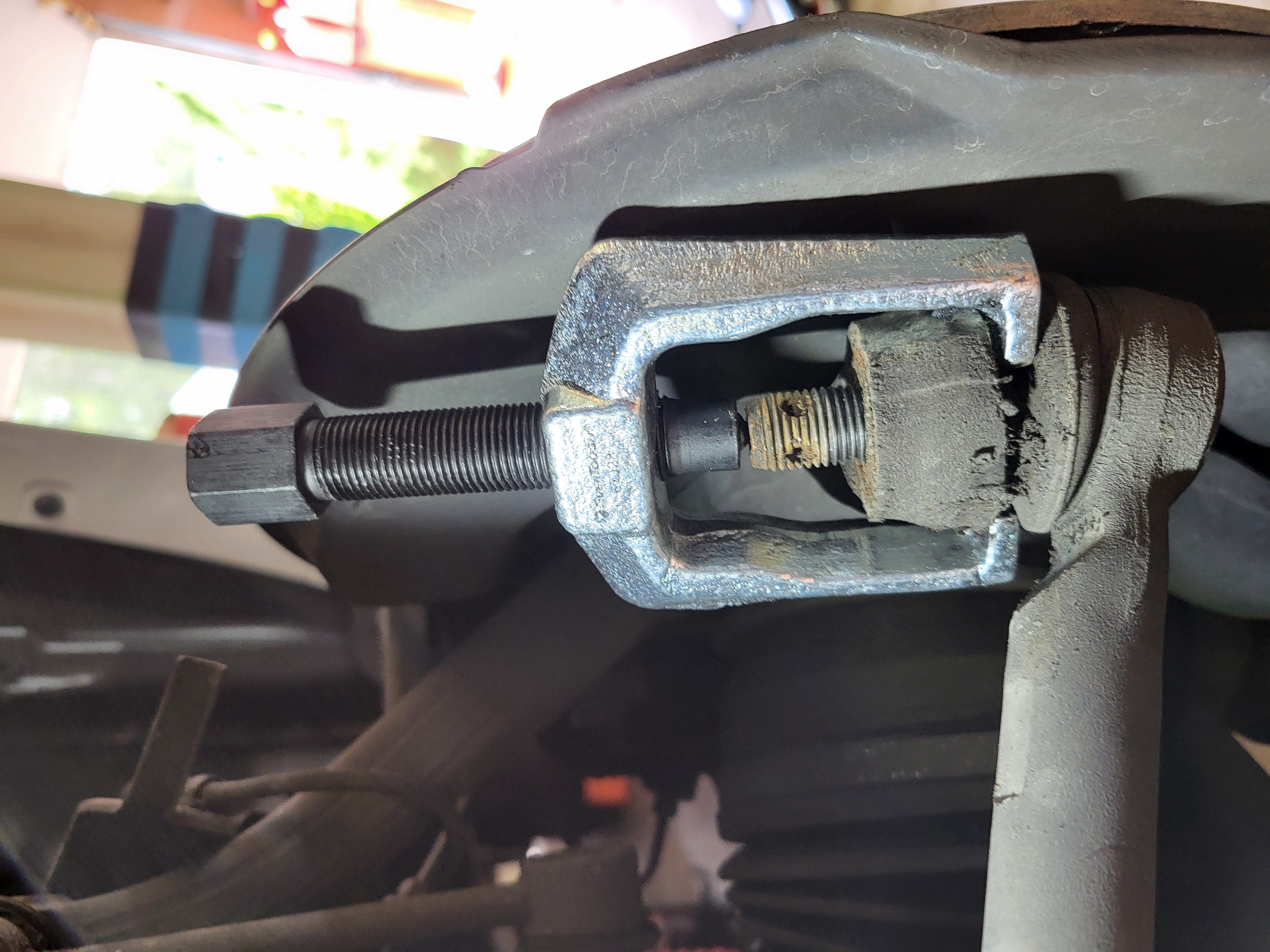
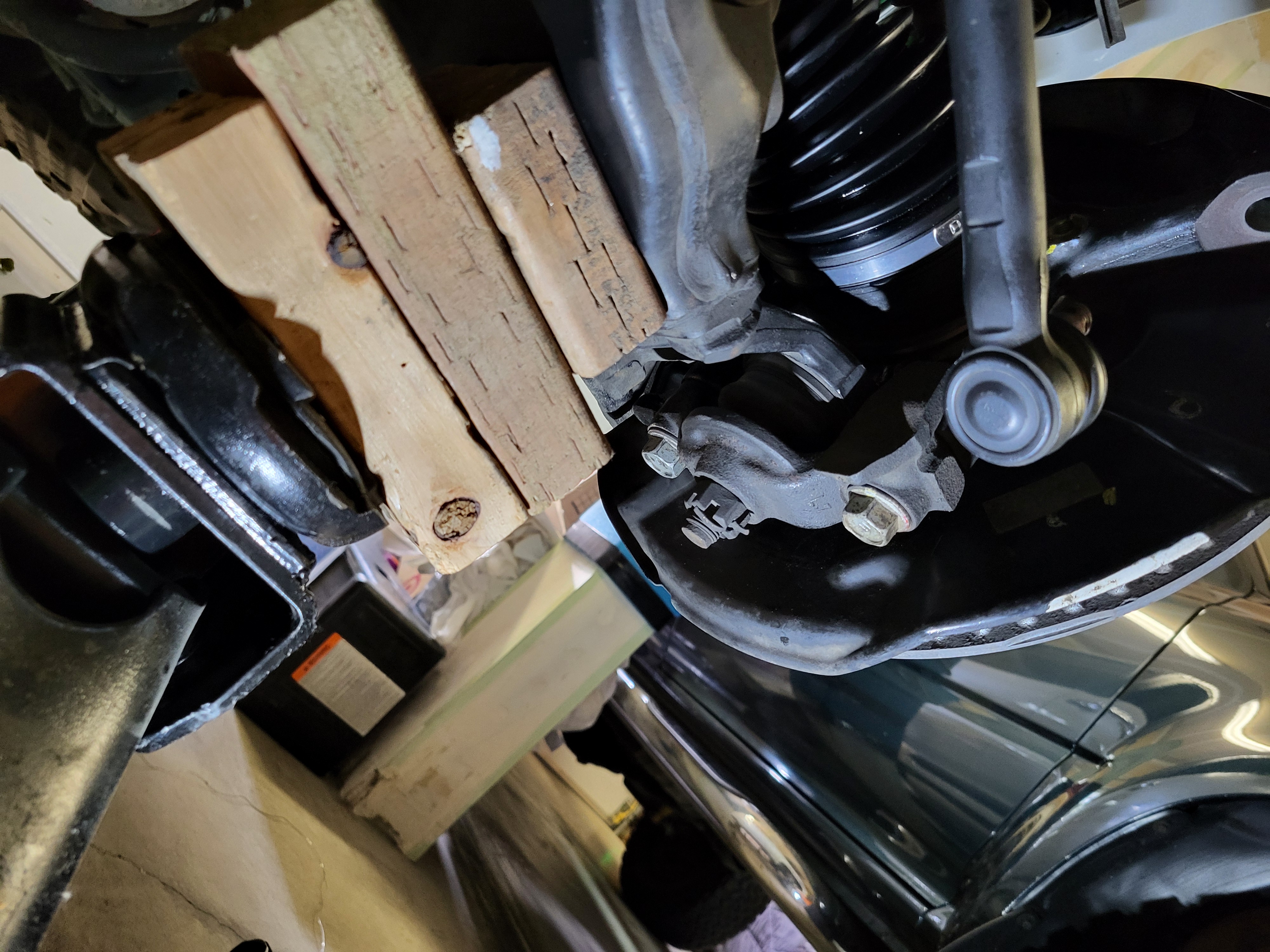
Step 10: Separate the tie rod
Remove the cotter pin with pliers and then remove the 19mm nut. After the nut has been removed, separate the tie rod by using a tie rod puller.
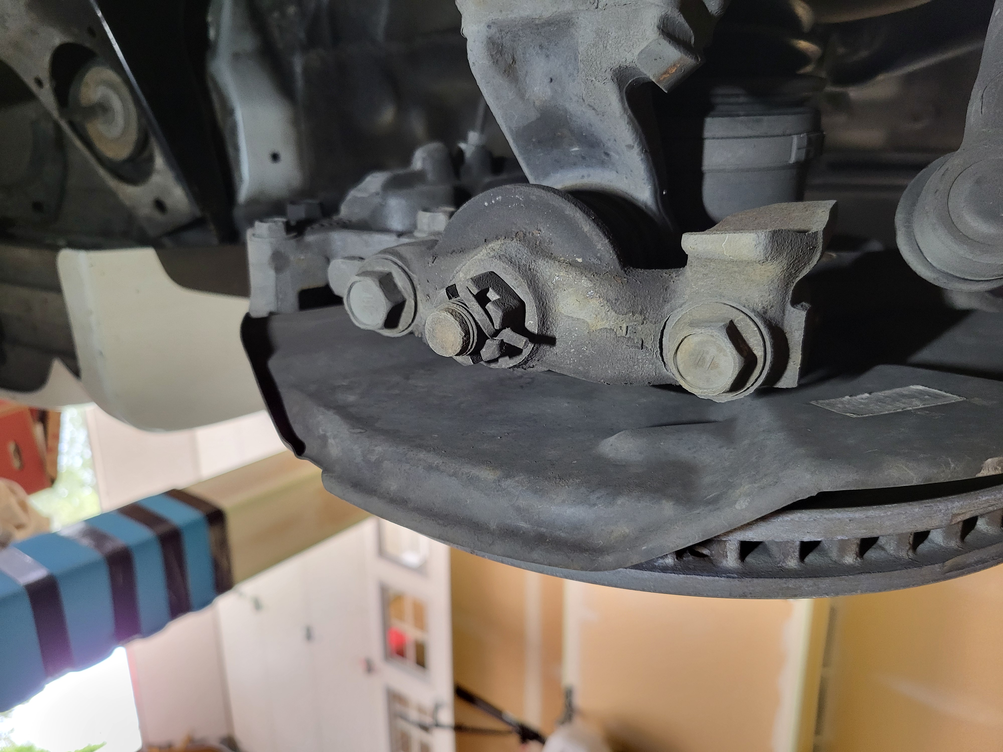
Step 11: Separate the front suspension lower arm
Remove the (2) 19mm bolts from under the lower arm. Once the bolts are removed, the steering knuckle will shift a little now that it is separated from the lower suspension arm.
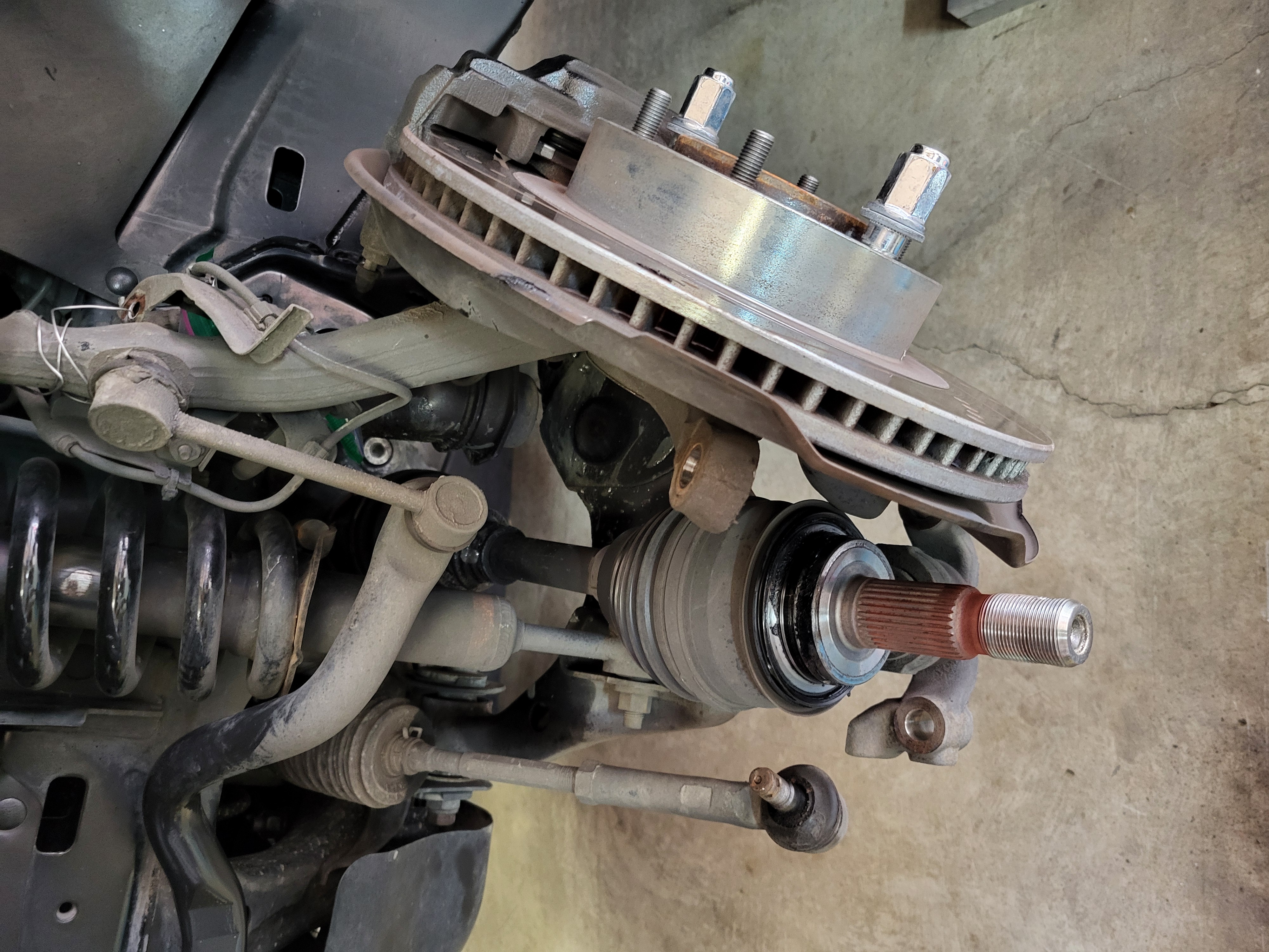
Step 12: Push the CV axle through the hub
This step can be easy or difficult depending on how seized the axle is in the hub. If easy, the axle can just be manually pushed through the hub. If it is a little more difficult, it can be hammered through the hub using a brass or dead-blow hammer (or a steel hammer if a large punch is used centered on the recess in the axle). If it is really stubborn, an axle puller can be used. The axle puller would mount the lug nut studs, and then a bolt in the center of the puller would push the axle through the hub.
Step 13: Move and secure the steering knuckle out of the way
Now that the steering knuckle is free of the axle, tie rod, and lower suspension arm, it can be moved out of the way to gain access to the CV axle. Move it as far away as possible and secure it with baling wire or bungie cords so that it doesn't interfere with subsequent steps. It can be move forward or aft, aft seems to provide the most clearance.
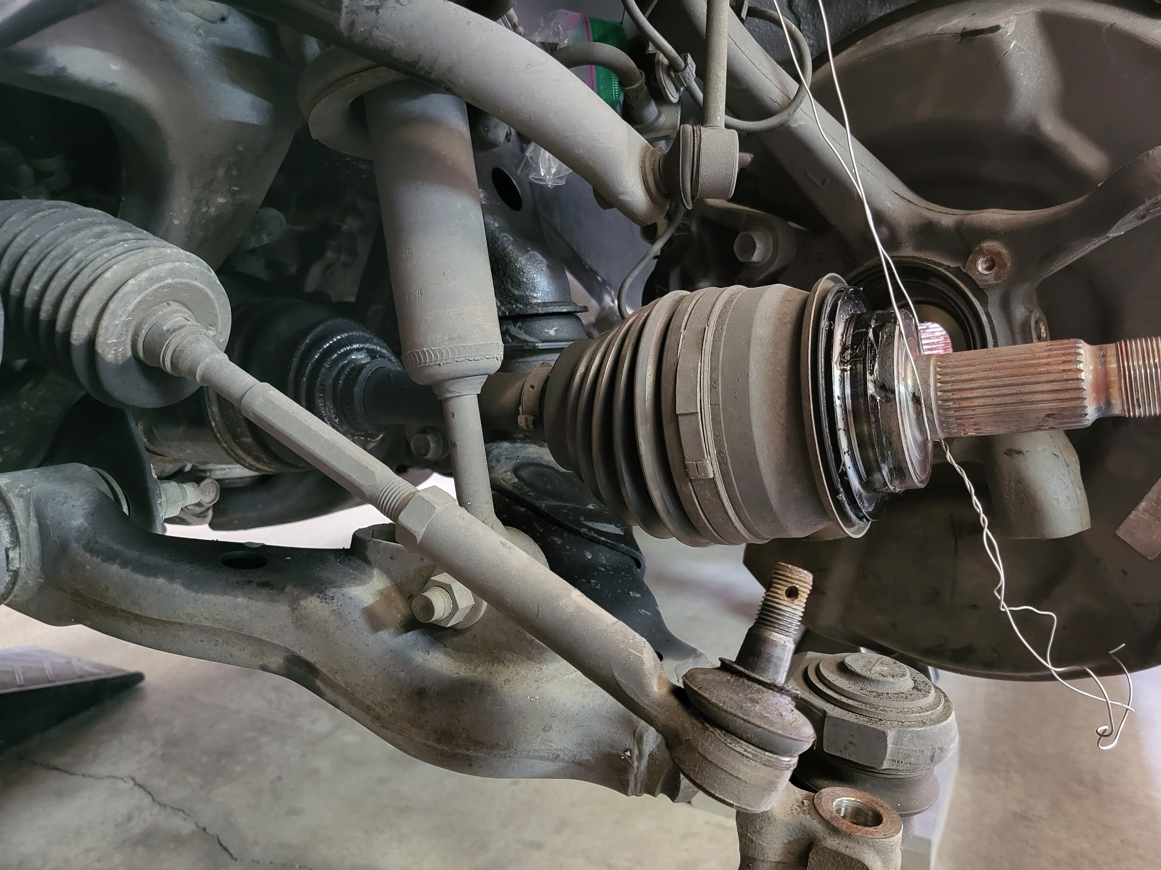
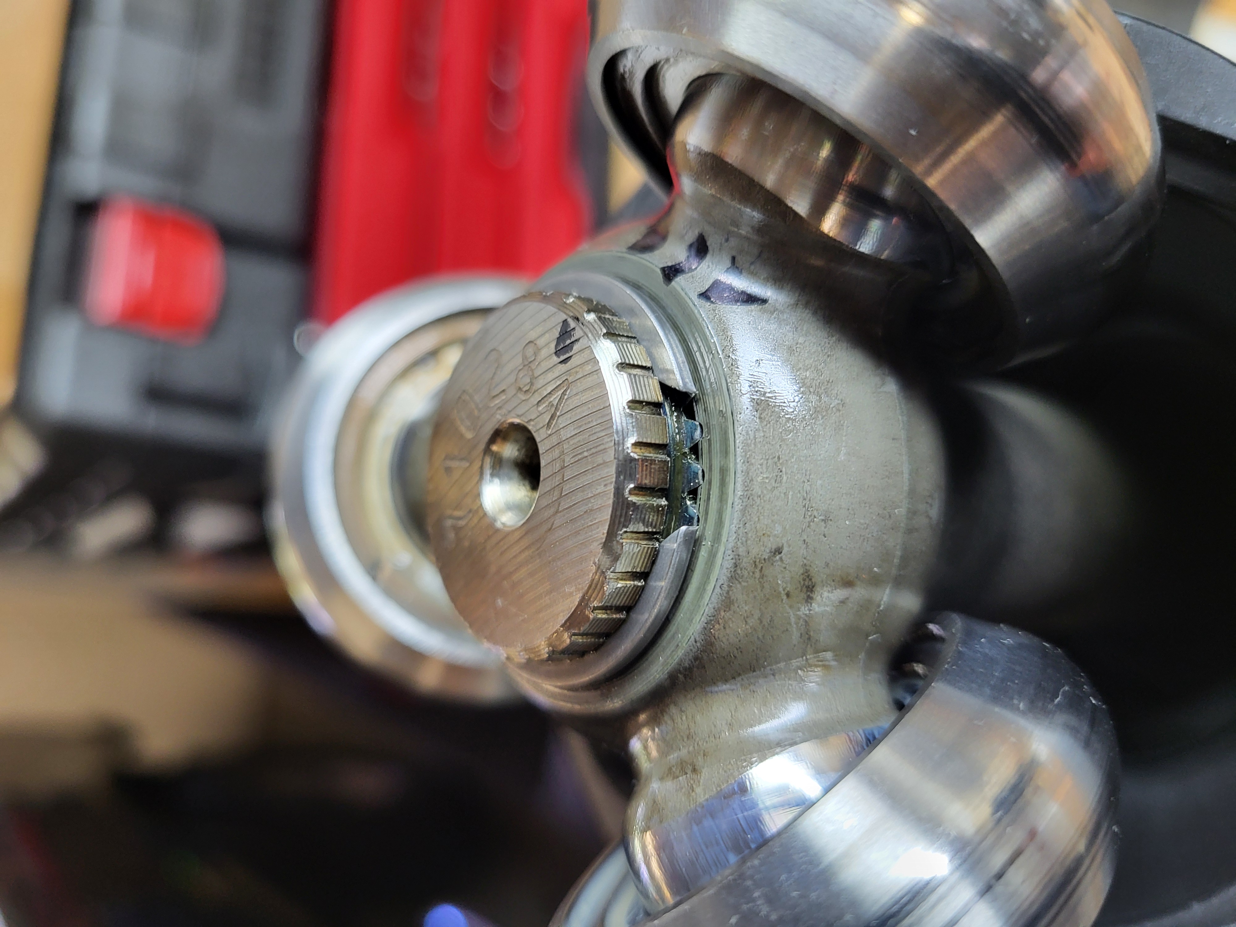
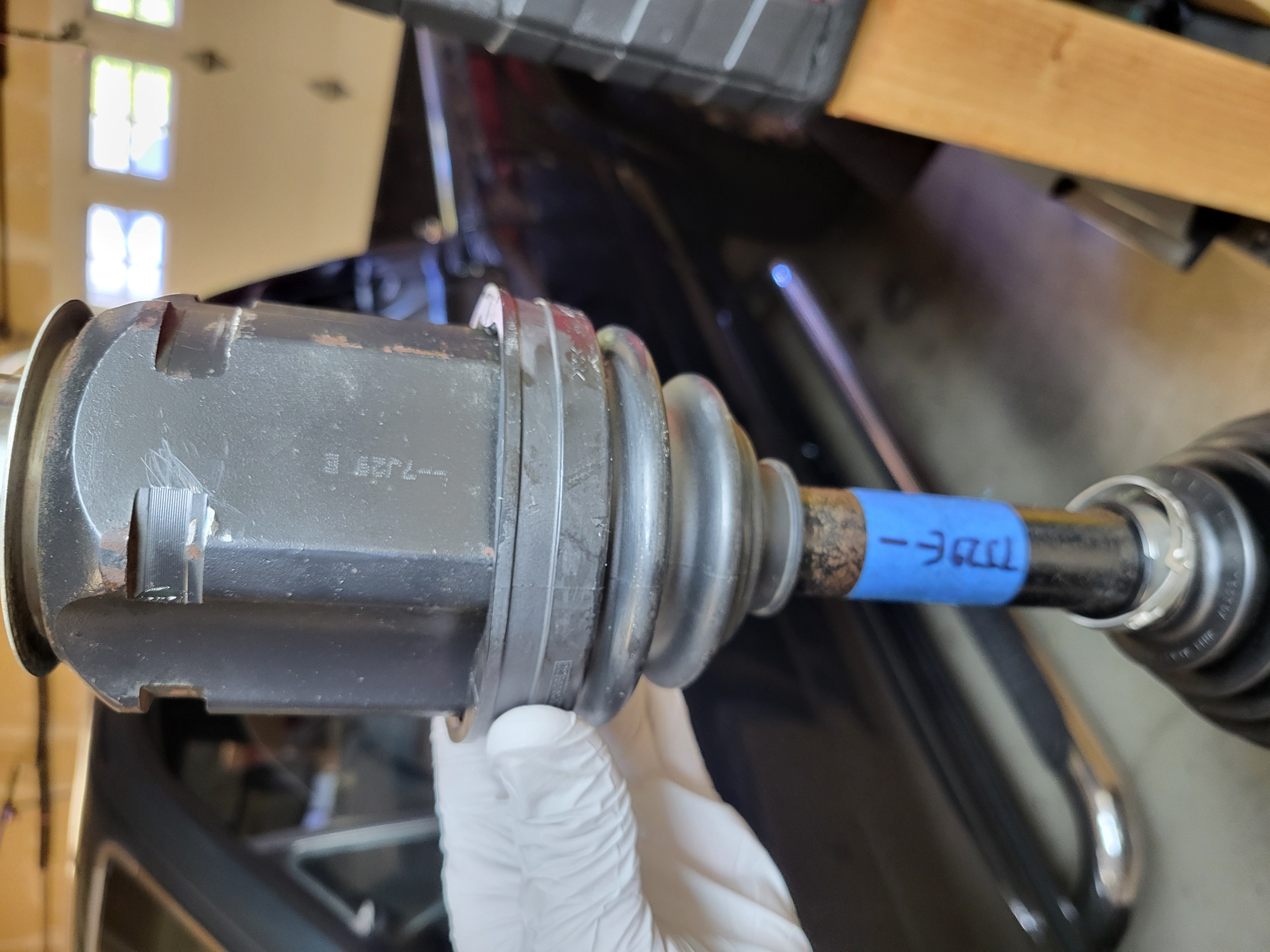
Step 14: Remove the CV axle from the differential
Use baling wire or rope to support the CV axle so it is straight, then remove the CV axle using one of the following methods:
1) Use the small notches in the inner housing to tap the axle out of the differential using a brass drift and a hammer. (doesn't work)
2) Attach a T-bolt hose clamp around the inner housing and then use the drift against the hose clamp, this provides more surface area to hit against. (doesn't work)
3) Get a pry bar onto the small notches, with a 2x4 braced on the differential and pry it out. (doesn't work)
4) Buy a 63mm CV axle puller tool and rent a slide hammer. (the tool doesn't fit the GX470 axle, therefore it doesn't work)
5) Put a long cold chisel in the small notches to get a better angle than the shorter brass drift and hit it with a hammer, note - this is more likely to damage the housing. (doesn't work and cuts into the housing)
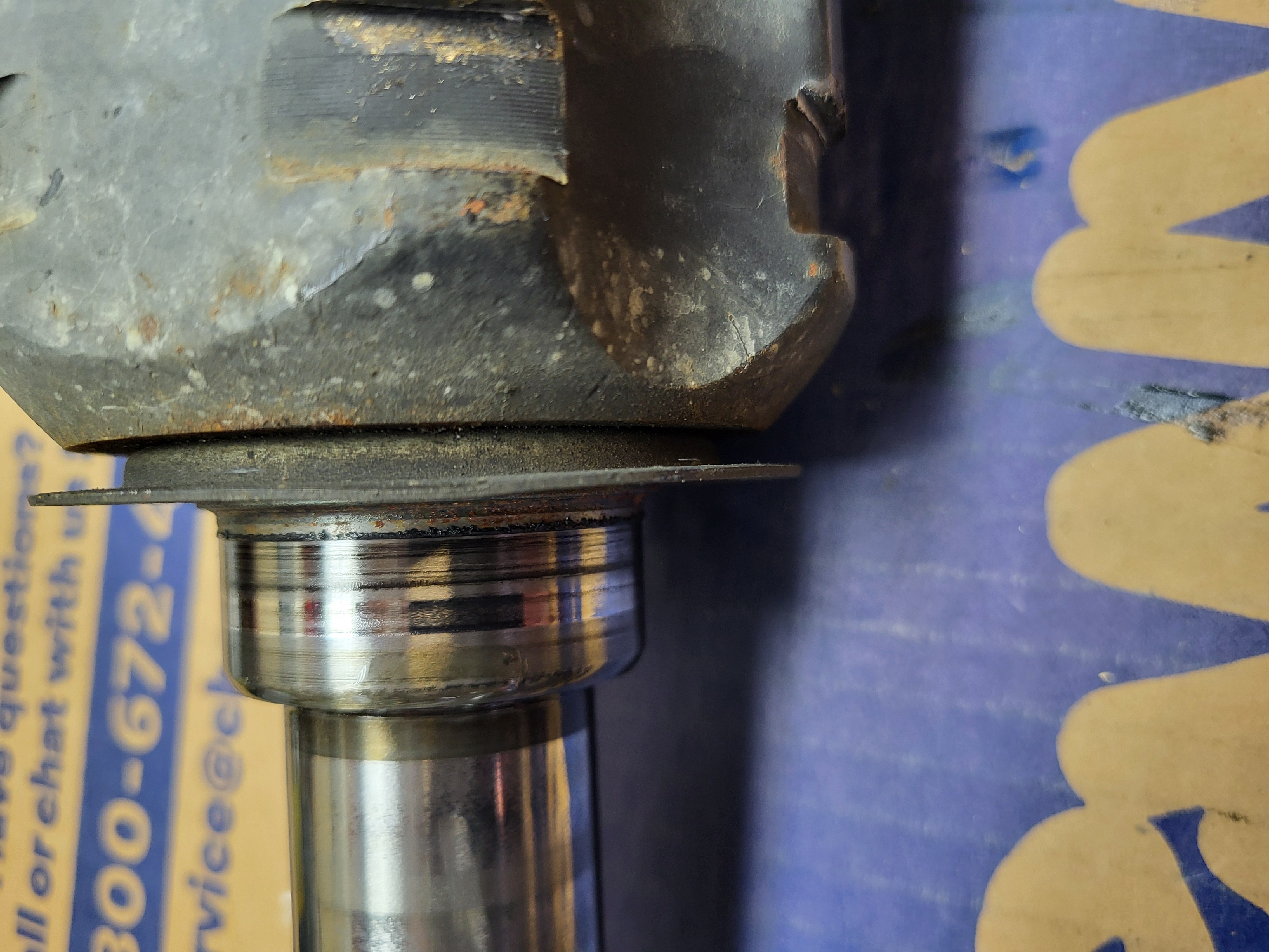
6) Do what everyone else does and put the pry bar in the gap between the differential and the CV axle knowing that you are going to put a small bend in the metal dust shield, then pry it just a little bit to get the axle C-clip disengaged. Once the axle moves just a little bit you can tap the small notches with a brass drift to get it the rest of the way out. (works like a charm with relatively small amount of force)
There may be a benefit of rotating the axle if the prying doesn't initially work, this can potentially get the retaining c-clip orientated up so that the axle can be more easily pried off.
CV Axle Reboot
Step 1: Clean the CV axle
Clean the accessible portions of the CV axle (the parts not under the boots). This will help with applying match marks in the next step.
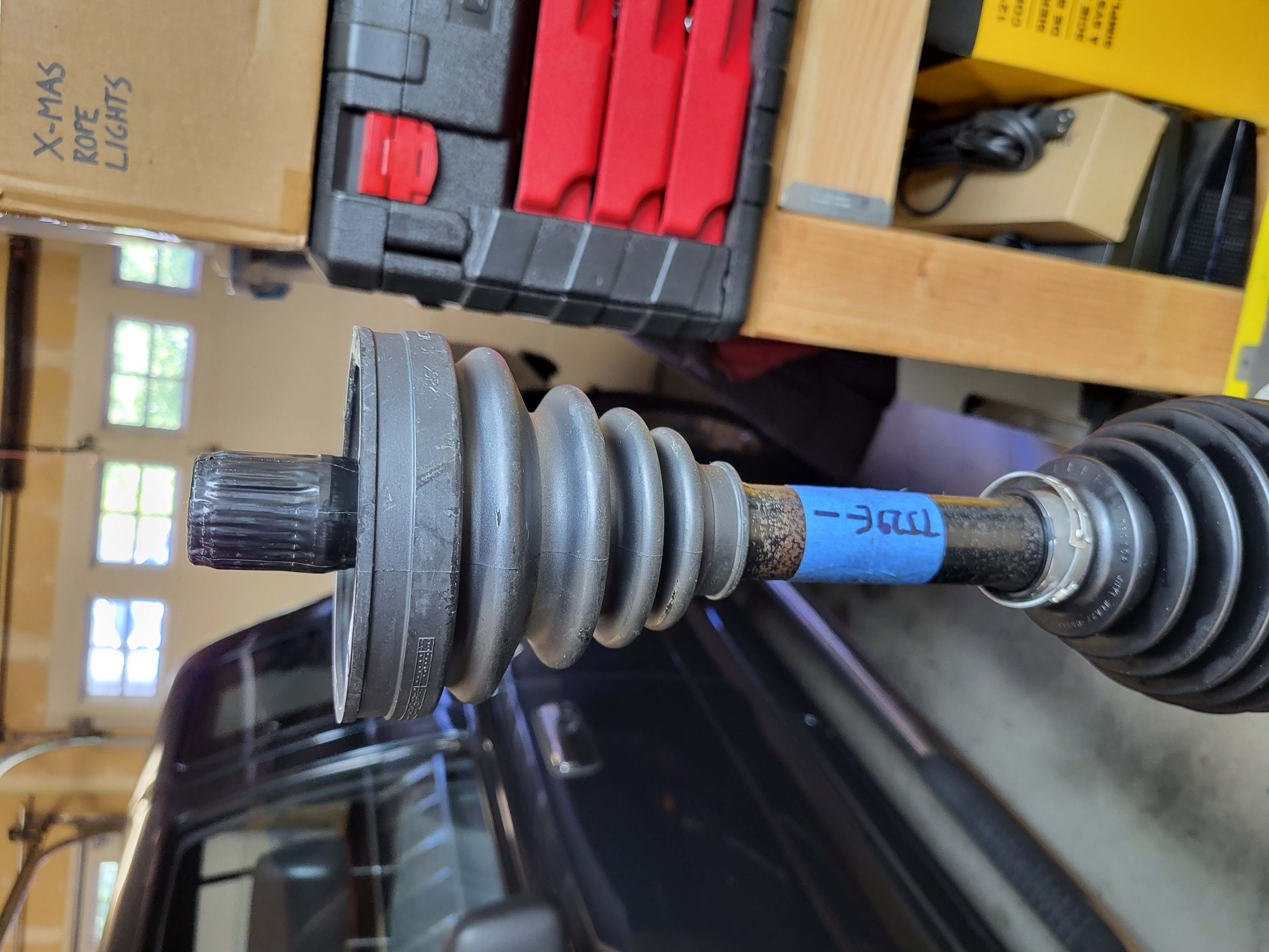
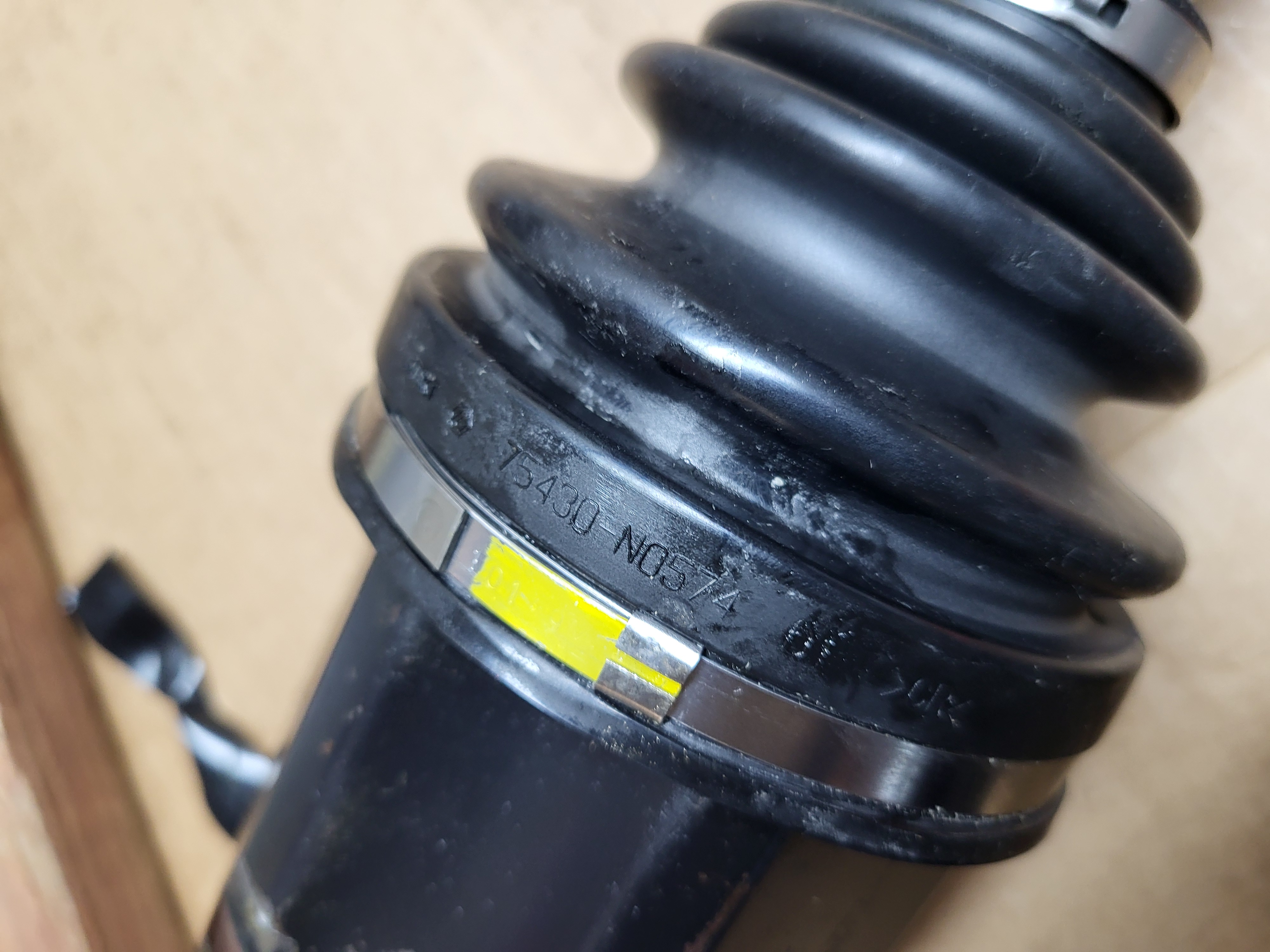
Step 2: Apply match marks to the CV axle and housing
According to the repair manual, match marks are to be applied on the housing, on the axle, and on the tripod. The tripod is not exposed yet, but the match marks can be applied to the axle and the housing with a marker or with tape. The housing does have an etched number that can be used as a match mark. This step may not be necessary, however it is noted in the repair manual.
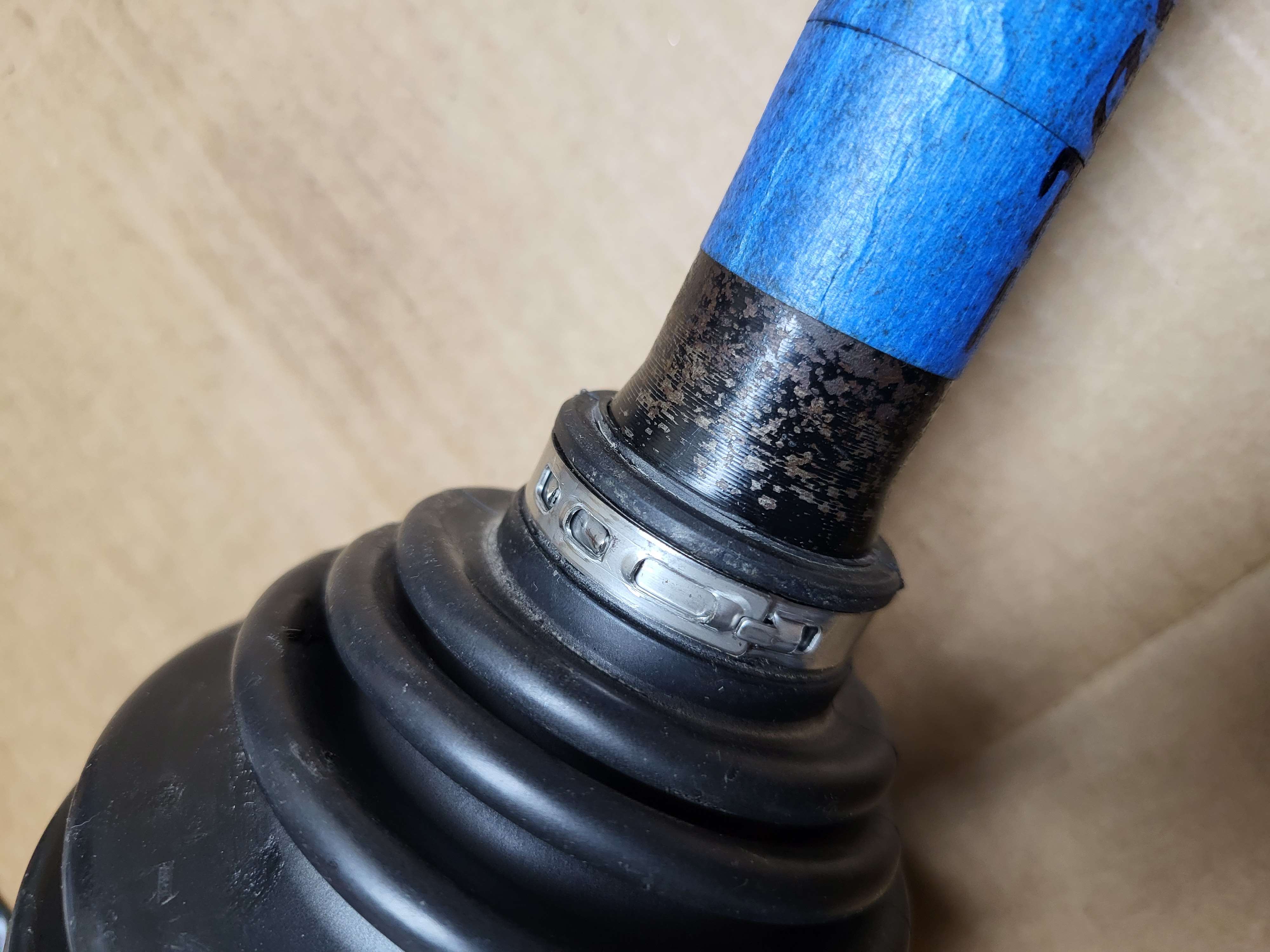
Step 3: Remove the inboard boot clamps
The service manual shows these clamps being removed with a screw driver, which works for the large clamps. The small clamps may need to be cut. A bolt cutter can be used to cut the protruding crimp.
Step 4: Remove the inboard axle with housing
With the boot unclamped, the inboard portion of the axle with the housing can be removed from the tripod.
Step 5: Cut off the inboard boot
Now that inboard axle is removed, most of the inner boot can be cut off (if not all). This will help with cleaning the tripod.
Step 6: Clean the exposed tripod
Now that the tripod has been exposed, it can be cleaned to help with applying the match mark.
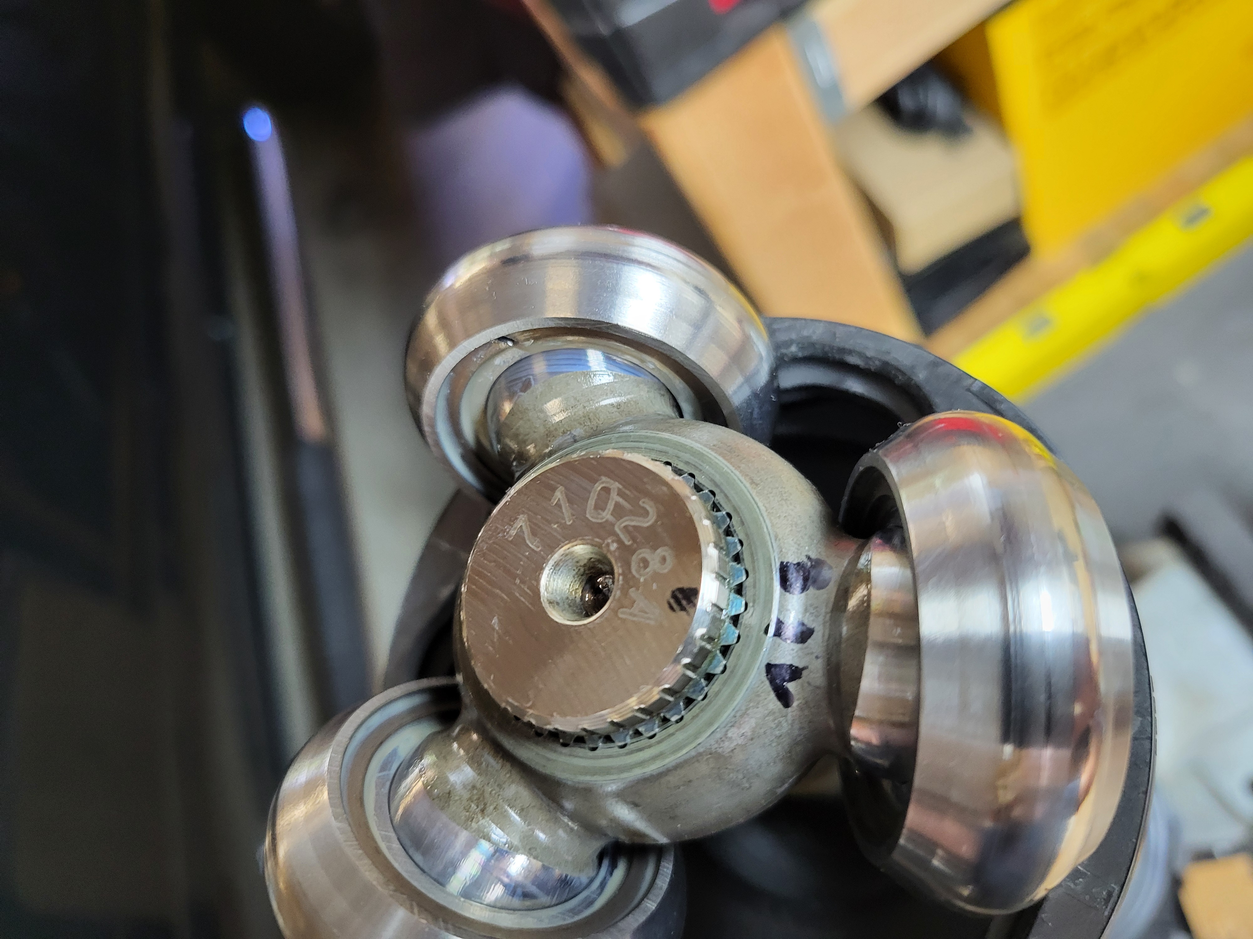
Step 7: Apply match marks to the tripod
Apply a match mark to the tripod that aligns with the match mark on the housing and the axle. One of the linked videos shows punching the match marks into the axle and tripod, however the manual states "Do not punch the marks."
Step 8: Remove the axle snap ring at the tripod
The tripod is retained to the axle with a snap ring. This ring must be removed to slide off the tripod; the tripod must be removed to allow the installation of the new CV boots.
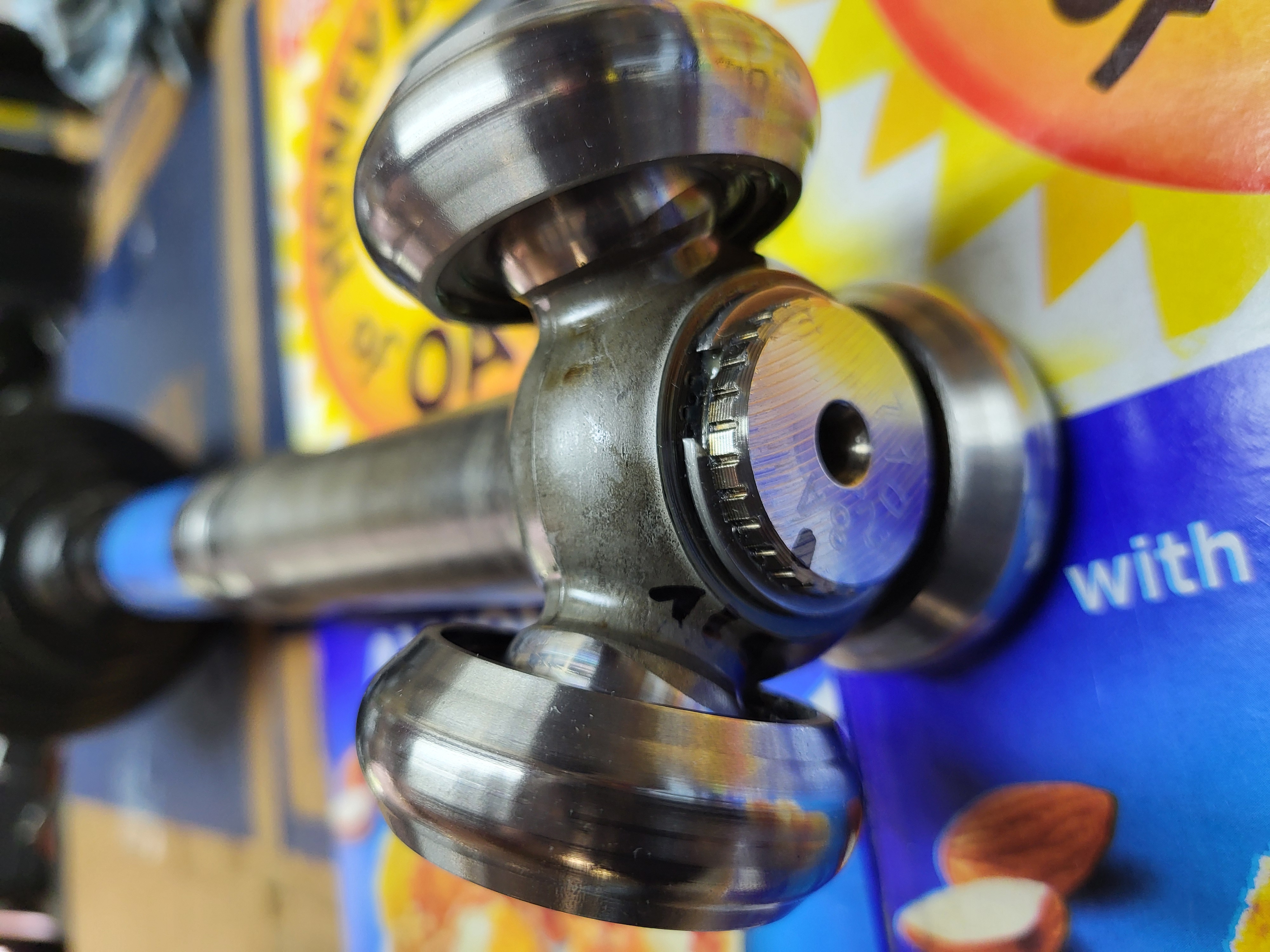
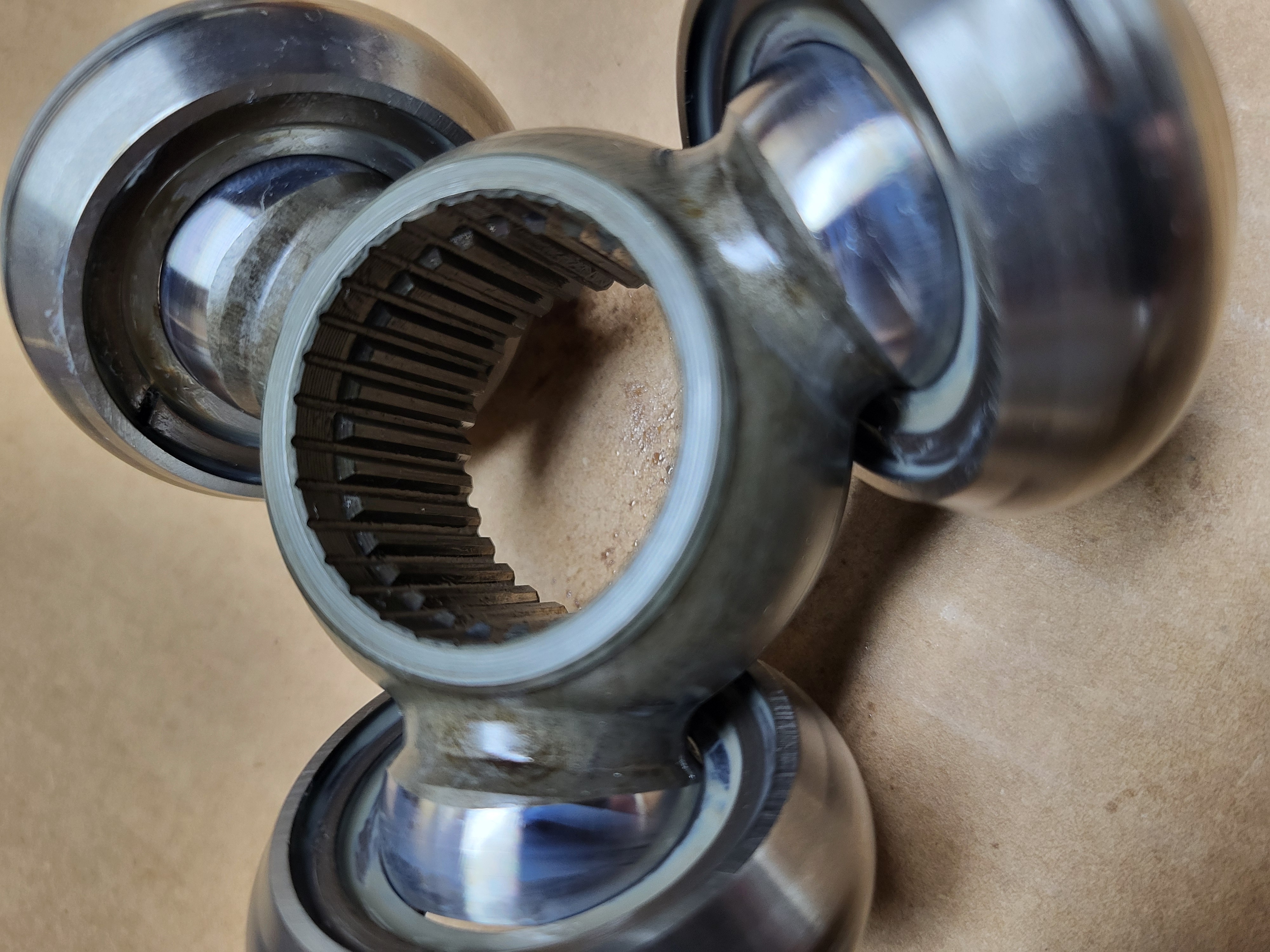
Step 9: Remove the tripod
The tripod may slide right off. If it does not, use a brass punch tap on the tripod housing near the axle shaft to slide the tripod off the axle shaft. Do not tap on the rollers.
Step 10: Remove the outboard boot clamps
Repeat the same process used to remove the inboard boot clamps.
Step 11: Remove the outer boot
The boot can be cut off or slid off the inboard side of the axle. If any of the outer boot is still clinging on, it can also be slid off the inboard side of the axle.
Step 12: Remove the old grease from the CV axle
Use shop rags and towels to clean as much grease as possible from all the exposed hardware. The inboard side and tripod can be cleaned pretty thoroughly; the outboard side will have some grease remaining under the bearing connection.
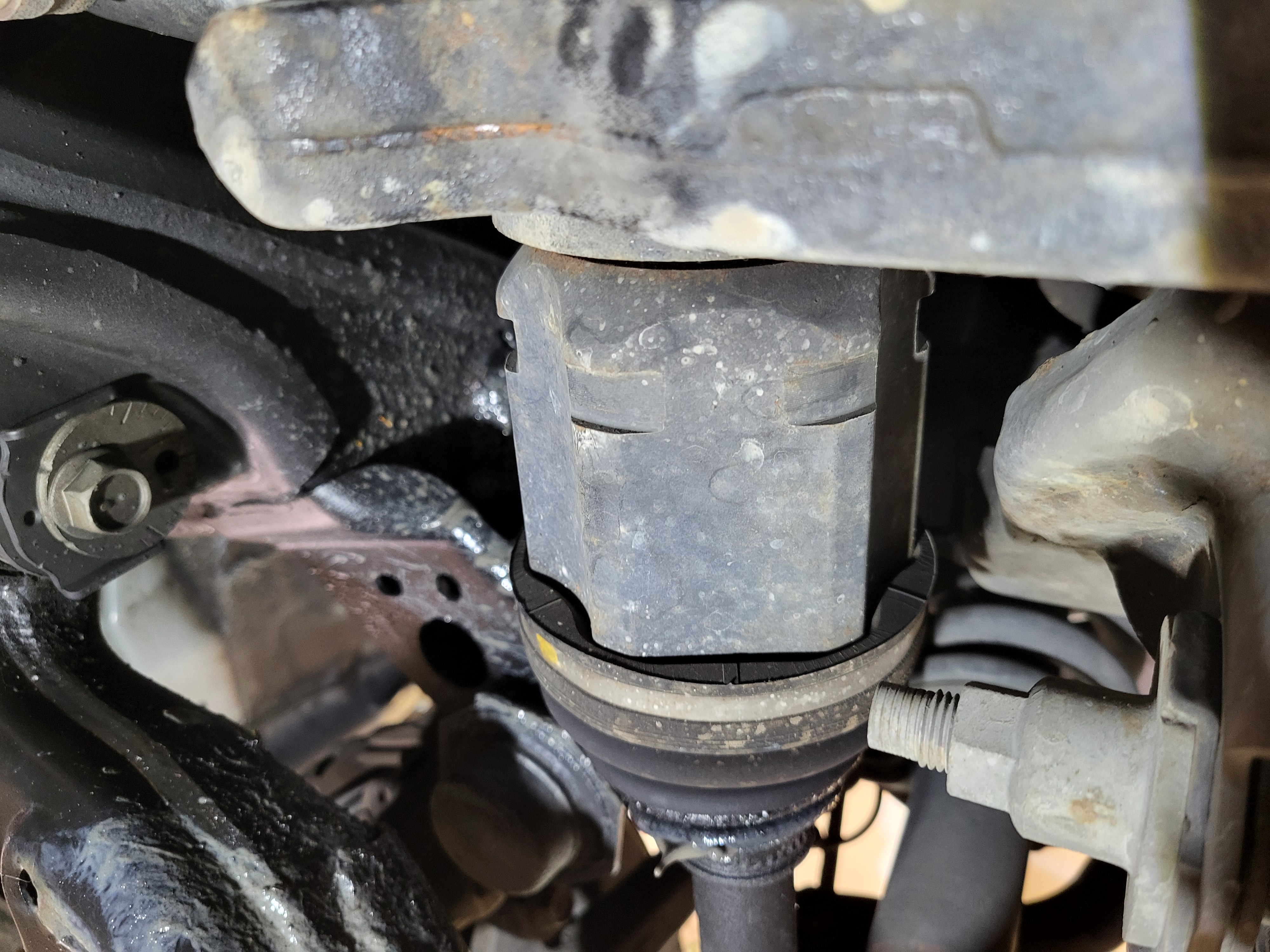
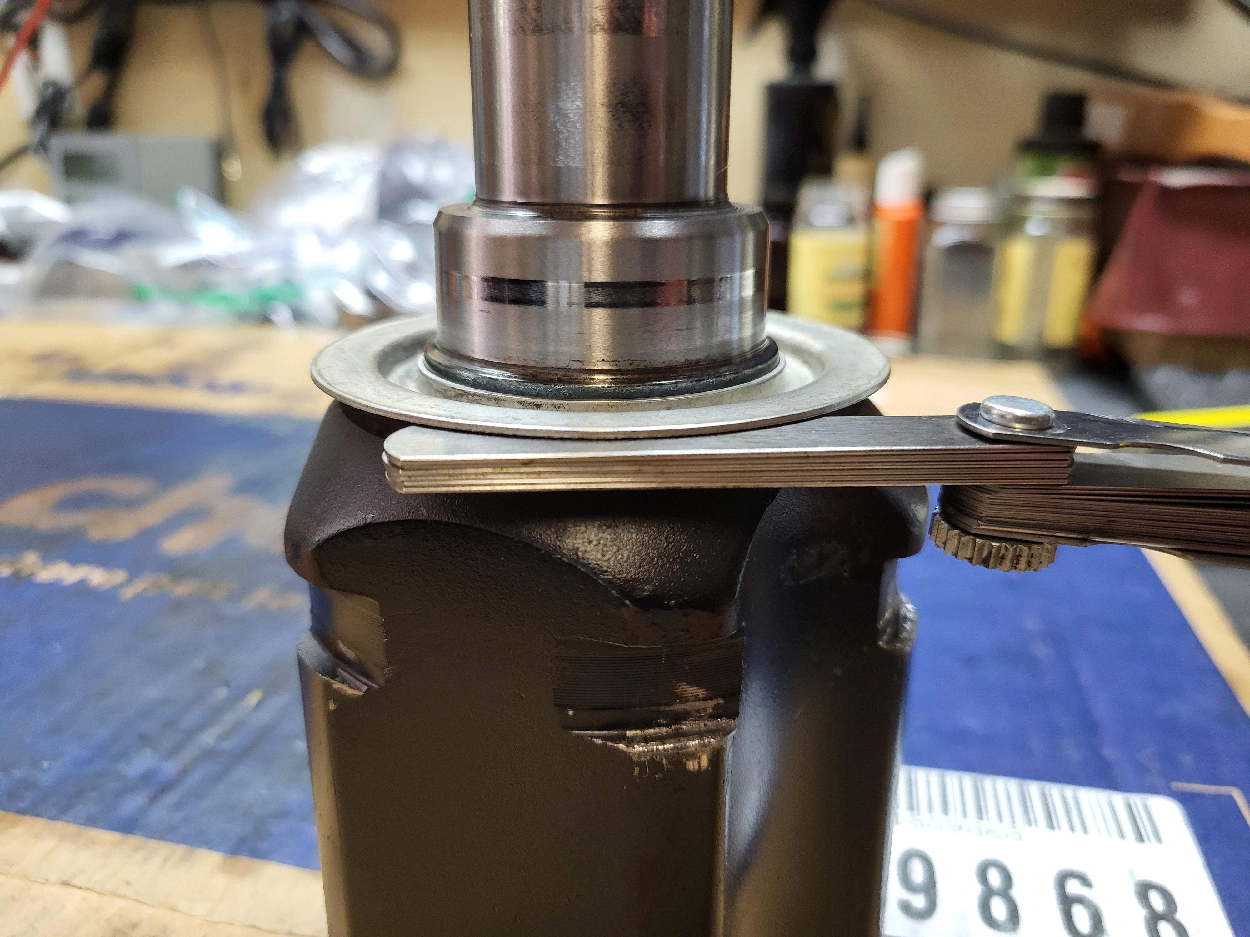
Step 13: Straighten or replace the inboard dust shield
The dust shield was likely bent during the removal of the axle. To straighten it, use a stack of feeler gauges underneath the bent area that match the nominal gap between the dust shield and housing. Then use a brass punch and a light hammer to tap the bend out of the shield with the feeler gauges preventing an overbend.
If replacing the shield, pry the old shield off. The repair manual shows using a bearing splitter and a press. Then install the new shield with the press. The repair manual shows the housing facing up with a flat plate spanning across it and the dust shield supported by the press plates. Press on the plate spanning the housing until the dust shield seats against the housing.
Note: The repair manual shows the dust shield as a non-reusable part.
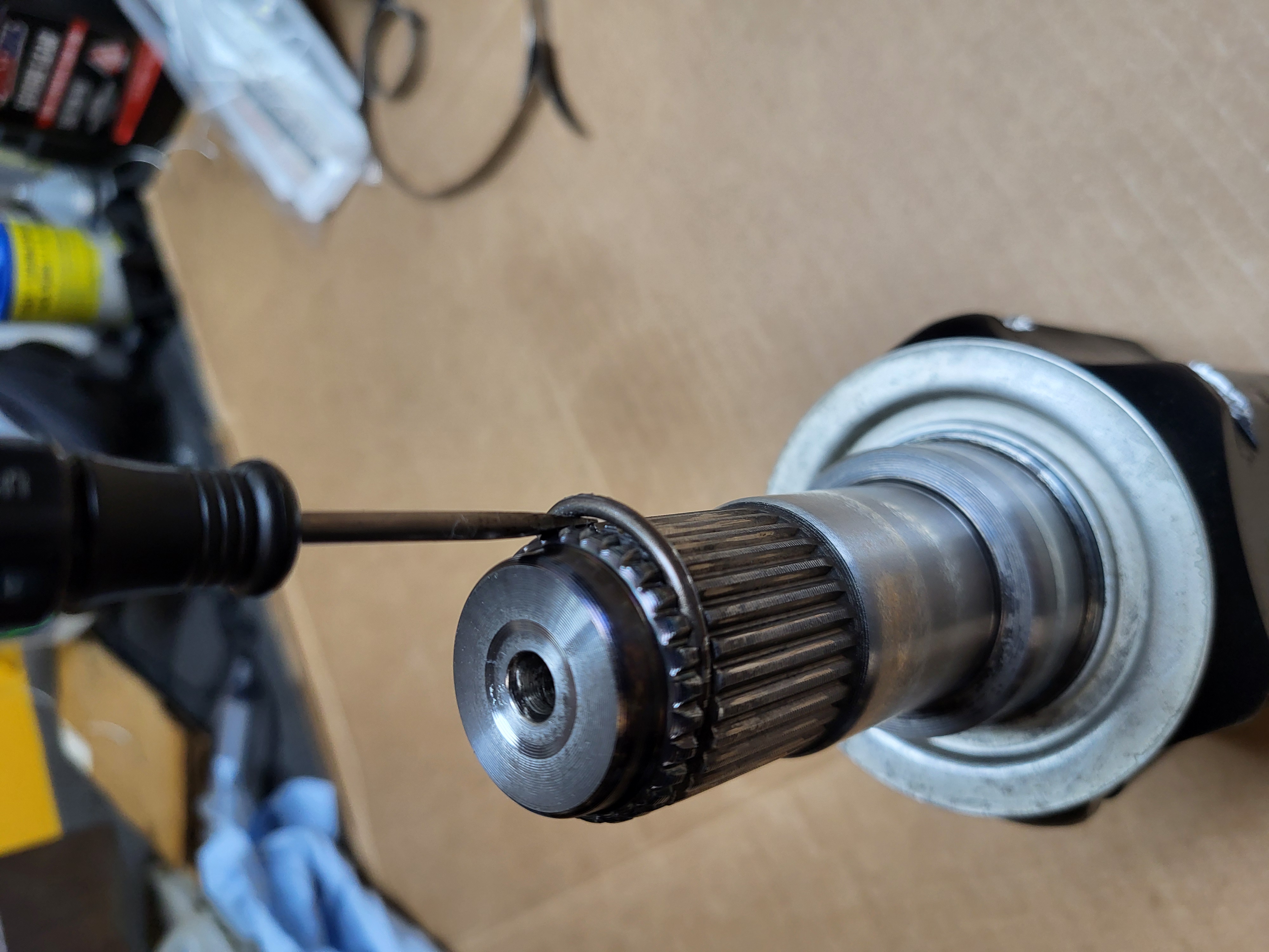
Step 14: Remove and replace the inboard C-clip
Using a screw driver, pry off the old C-clip; basically stretch the clip until it can be removed. Then install the new one by aligning it with the groove in the shaft and pushing it on. If necessary, it can be tapped on with a brass hammer.
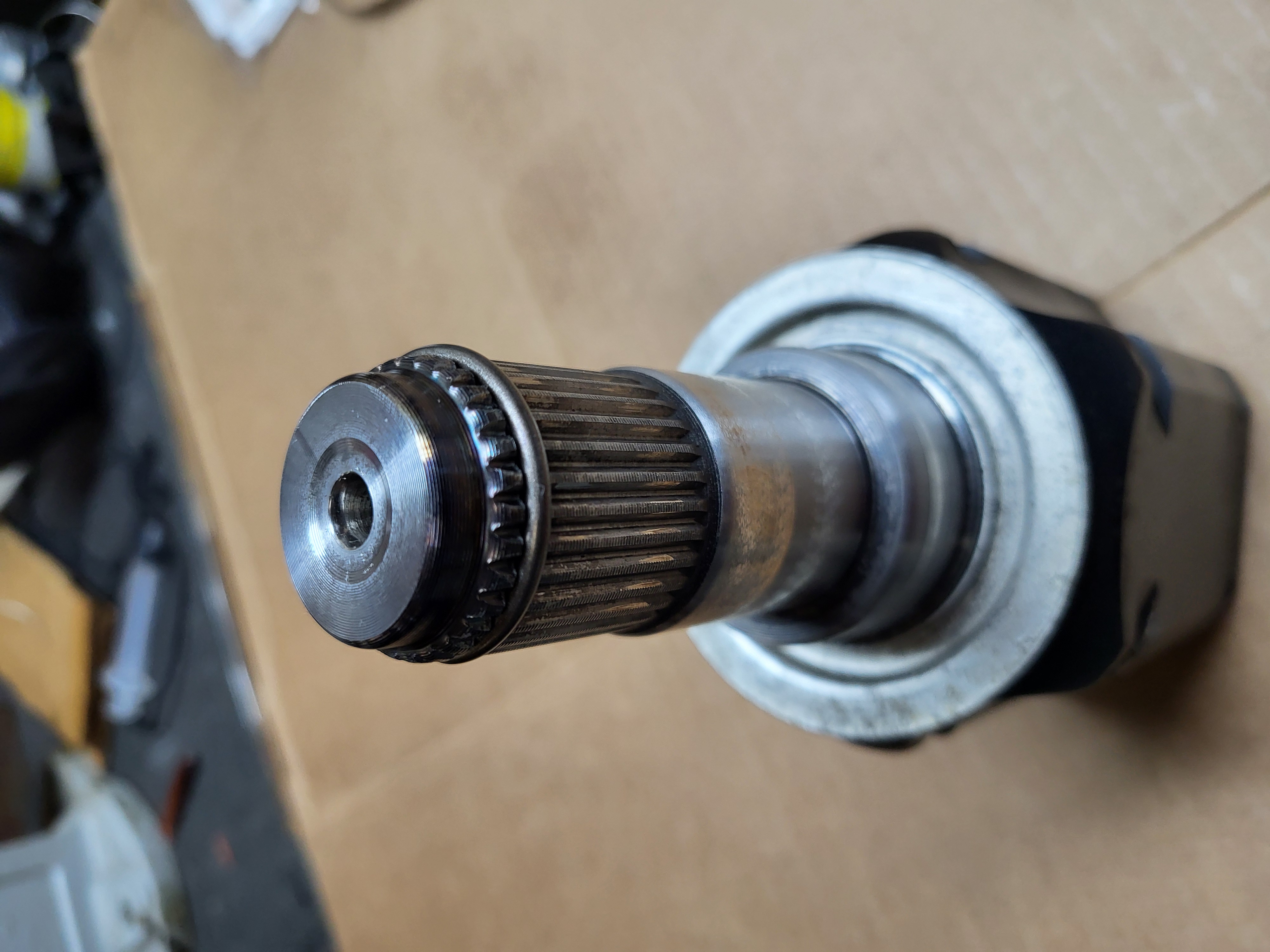
Step 15: Reused or remove and replace the outboard oil seal dust shield
Clean and inspect the outboard oil seal dust shield, it may be resused if shield is in good condition.
If damaged, remove the shield using a screw driver and hammer. Clean the interface and install the new oil seal dust shield. The knuckle seal (removed in later operations), can help with the installation of the new shield, see this link Outboard oil seal dust shield installation tip.
Note: The repair manual shows the oil seal dust shield as a non-reusable part.
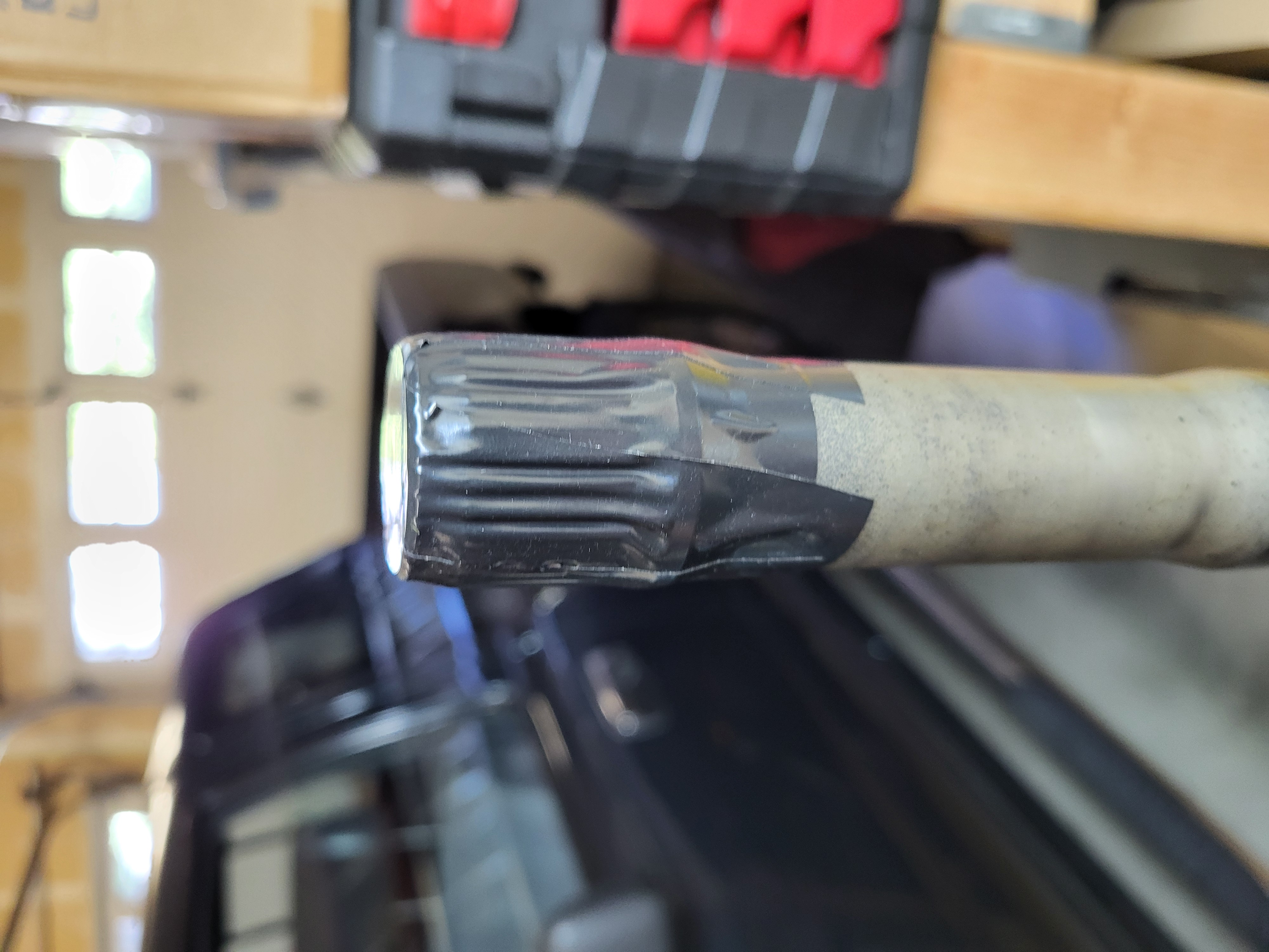
Step 16: Cover the inboard splines with electrical tape
The repair manual states to cover the inboard splines with electrical tape before sliding on the outboard boot to prevent the boot from getting cut.
This step may not be necessary for the outer boot, but the inner boot fits pretty snug over the splines. Note this step is included in the repair manual.
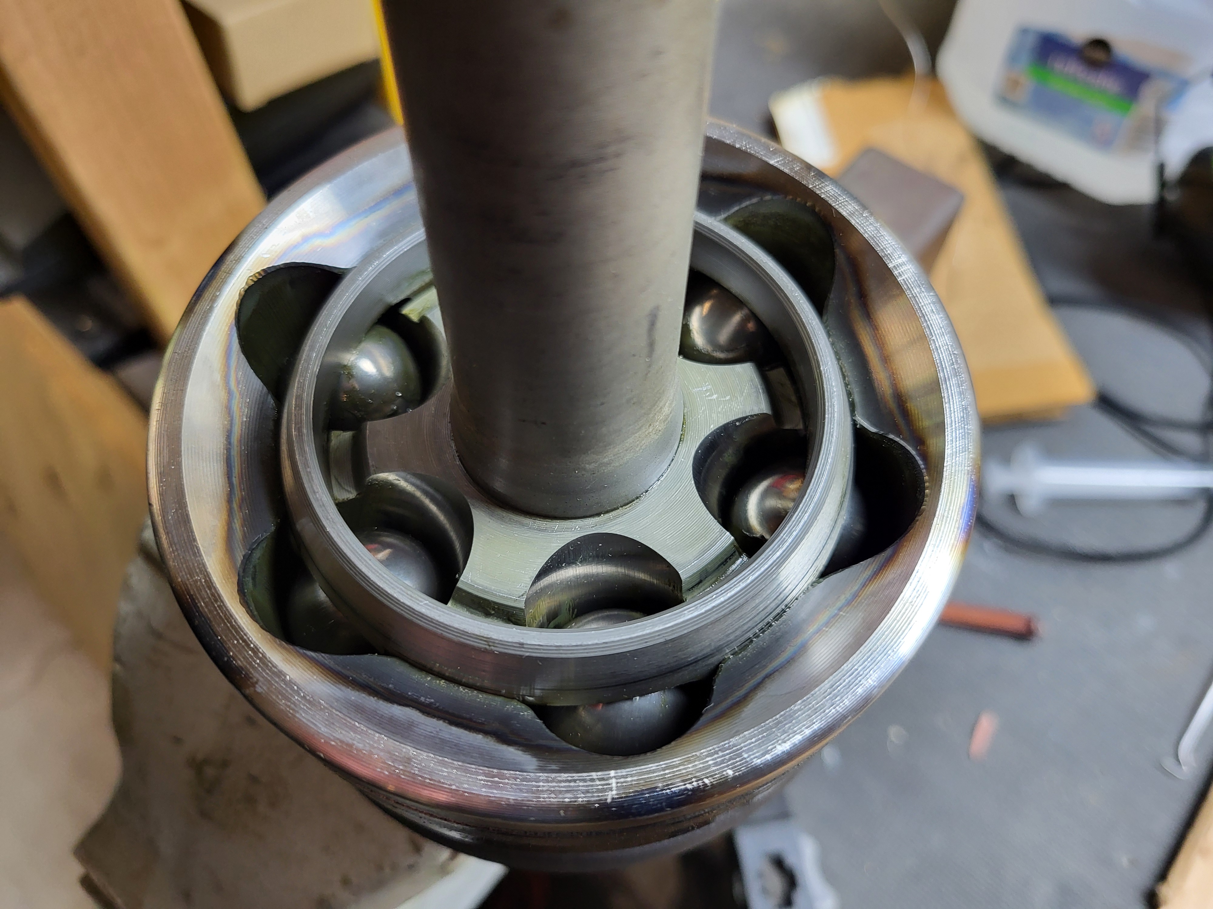
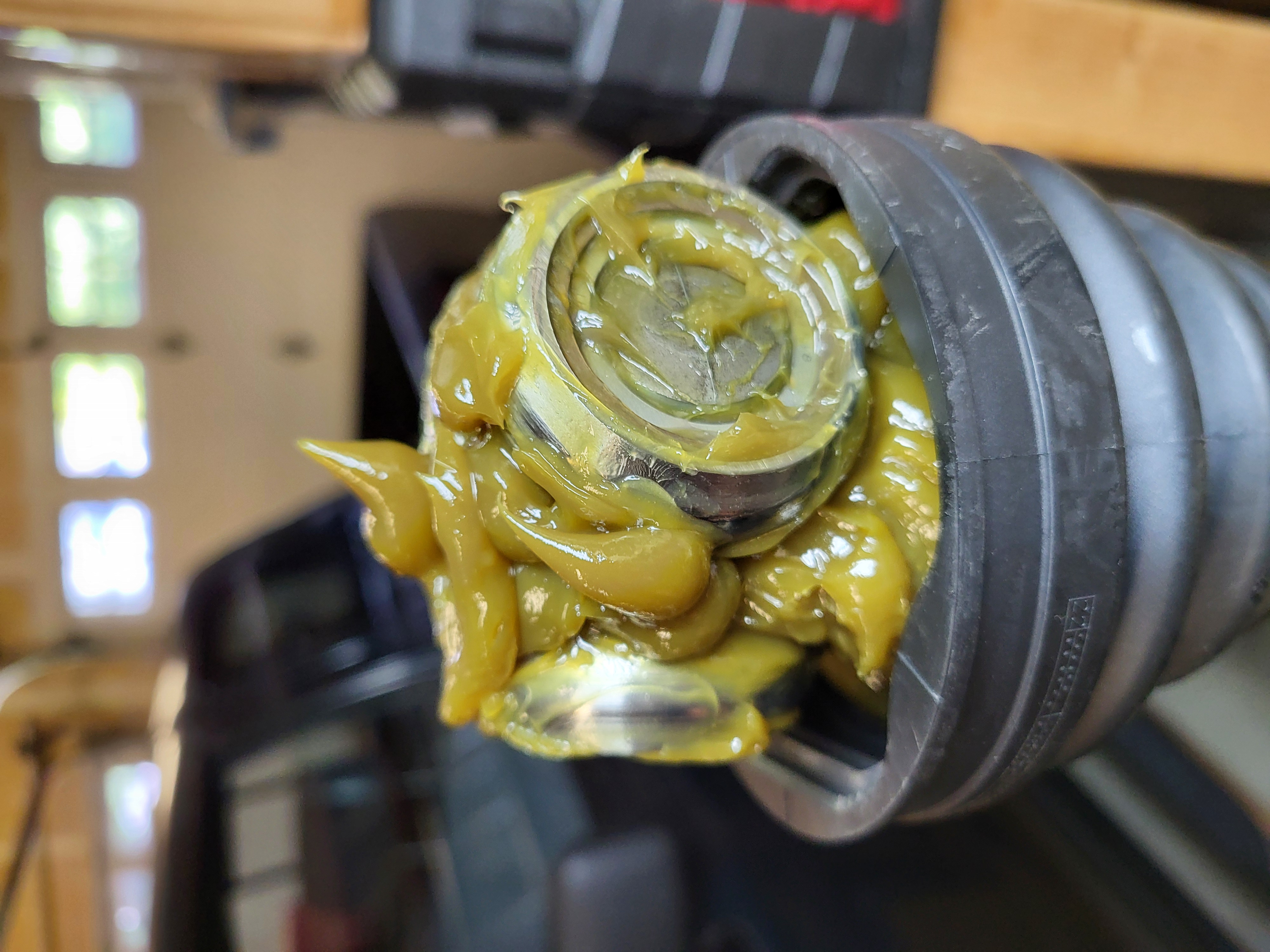
Step 17: Apply grease to the outboard CV joint
The outboard joint uses the gray colored grease in the white tube that is included with the boot kit. There are a couple ways to apply this grease:
1) Secure the outboard side of the CV axle in a vice and apply the grease to the bearings mounding it up along the axle, then slide the outboard boot down the axle and snap it into the retaining grooves in the axle and in the housing. This method allows the grease to be worked into the bearings if desired, but it is not necessary.
2) Slide the outboard boot onto the axle and snap the small end into the groove on the axle. Put the inboard side of the axle in a vice, then tilt the outboard end of the axle to create a gap between the boot and the housing. Apply the grease through the gap filling the boot. Once it is full, snap the boot into the housing retaining groove.
To get all the grease out of the tube, set it on a table and use a screwdriver handle to push the grease to the end of the tube, then squeeze it out onto the axle.
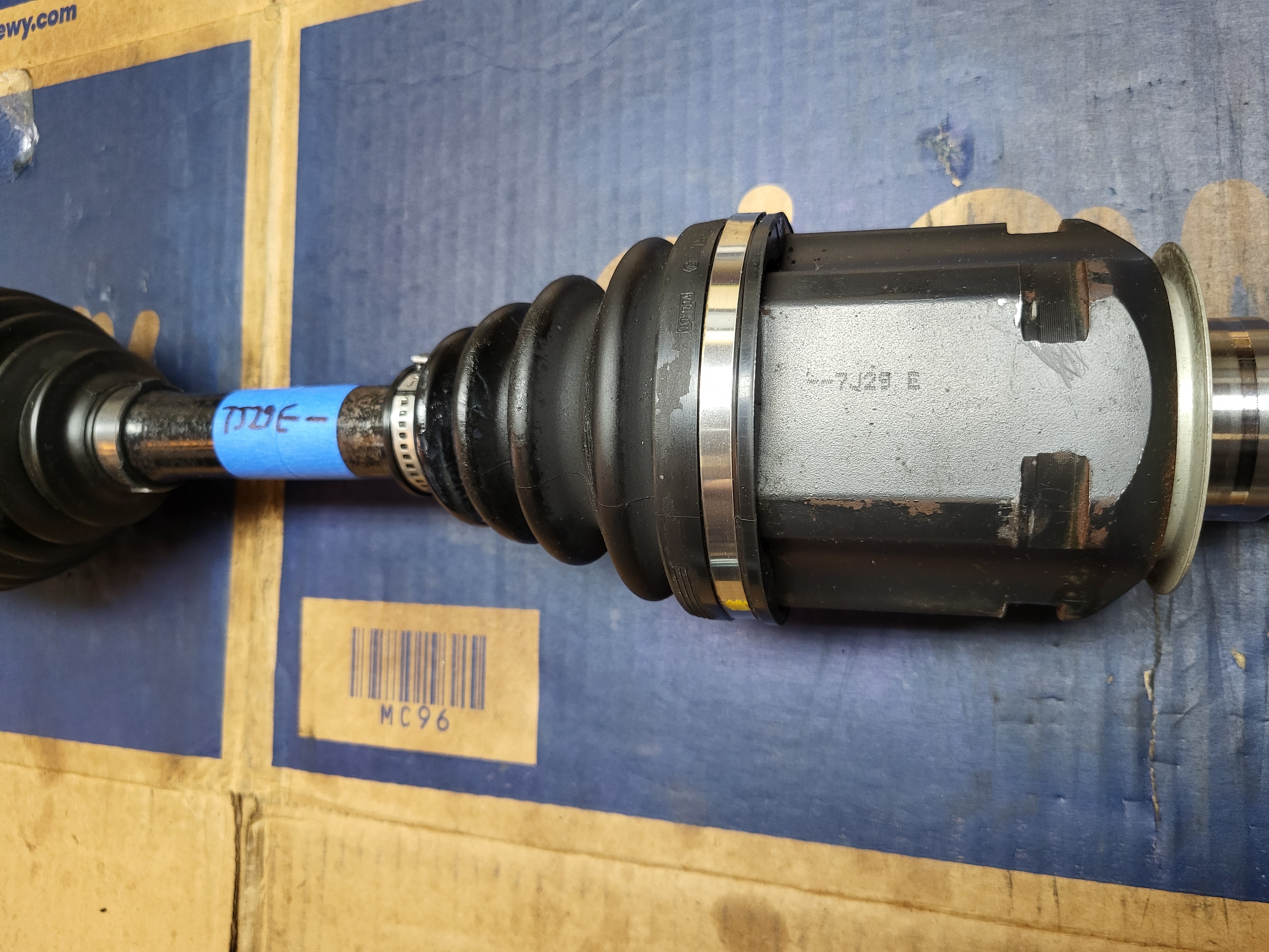
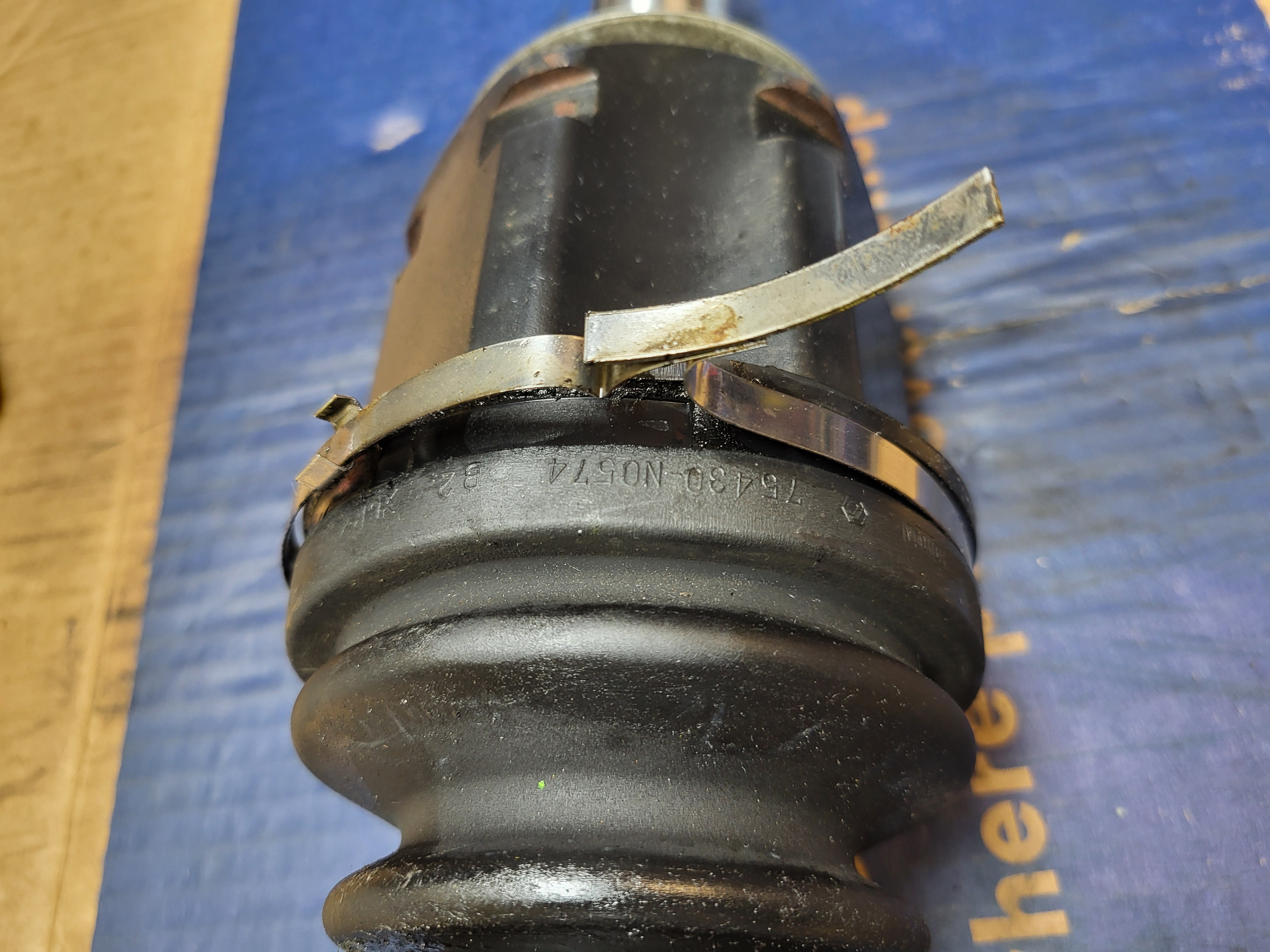
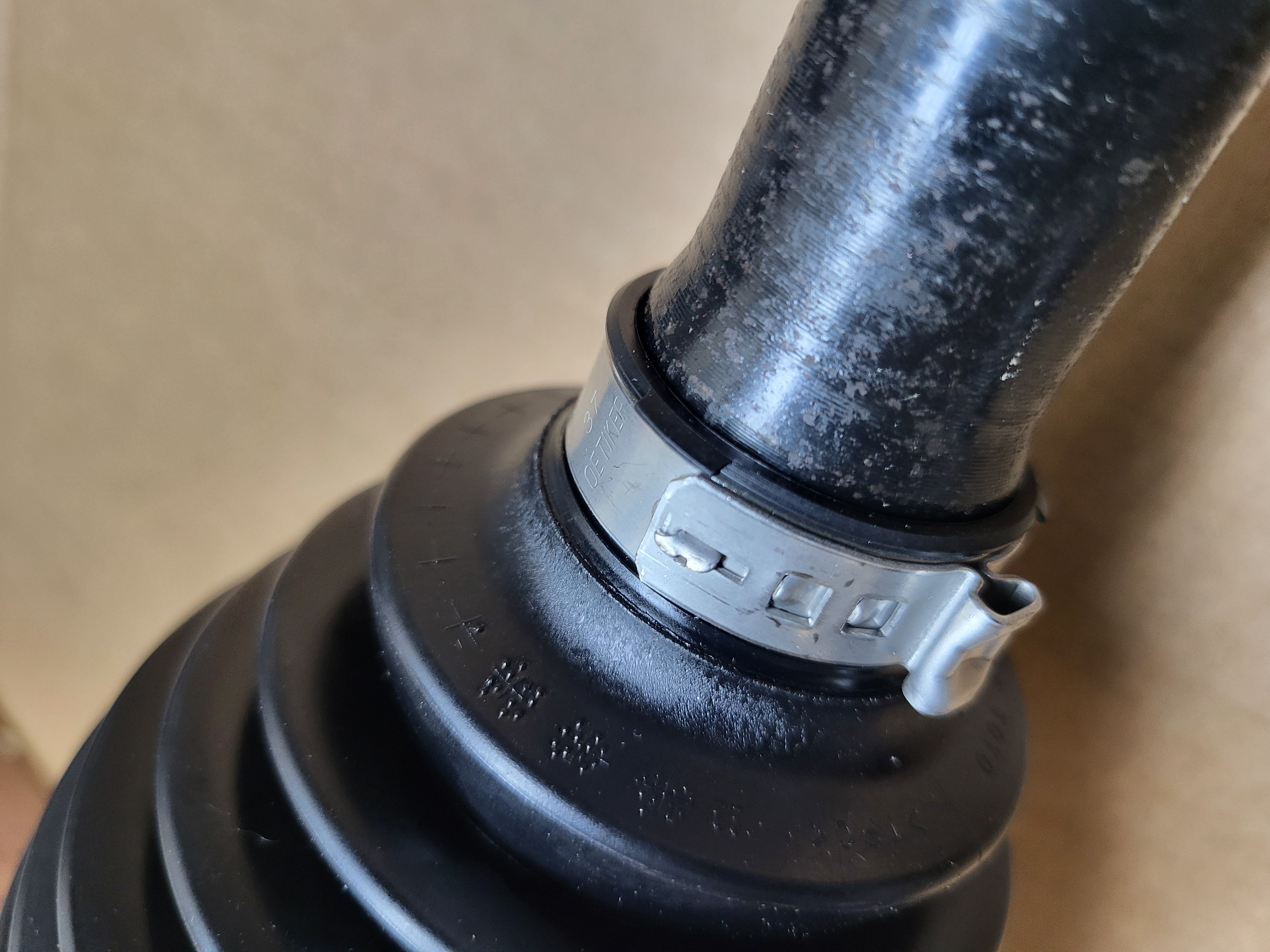
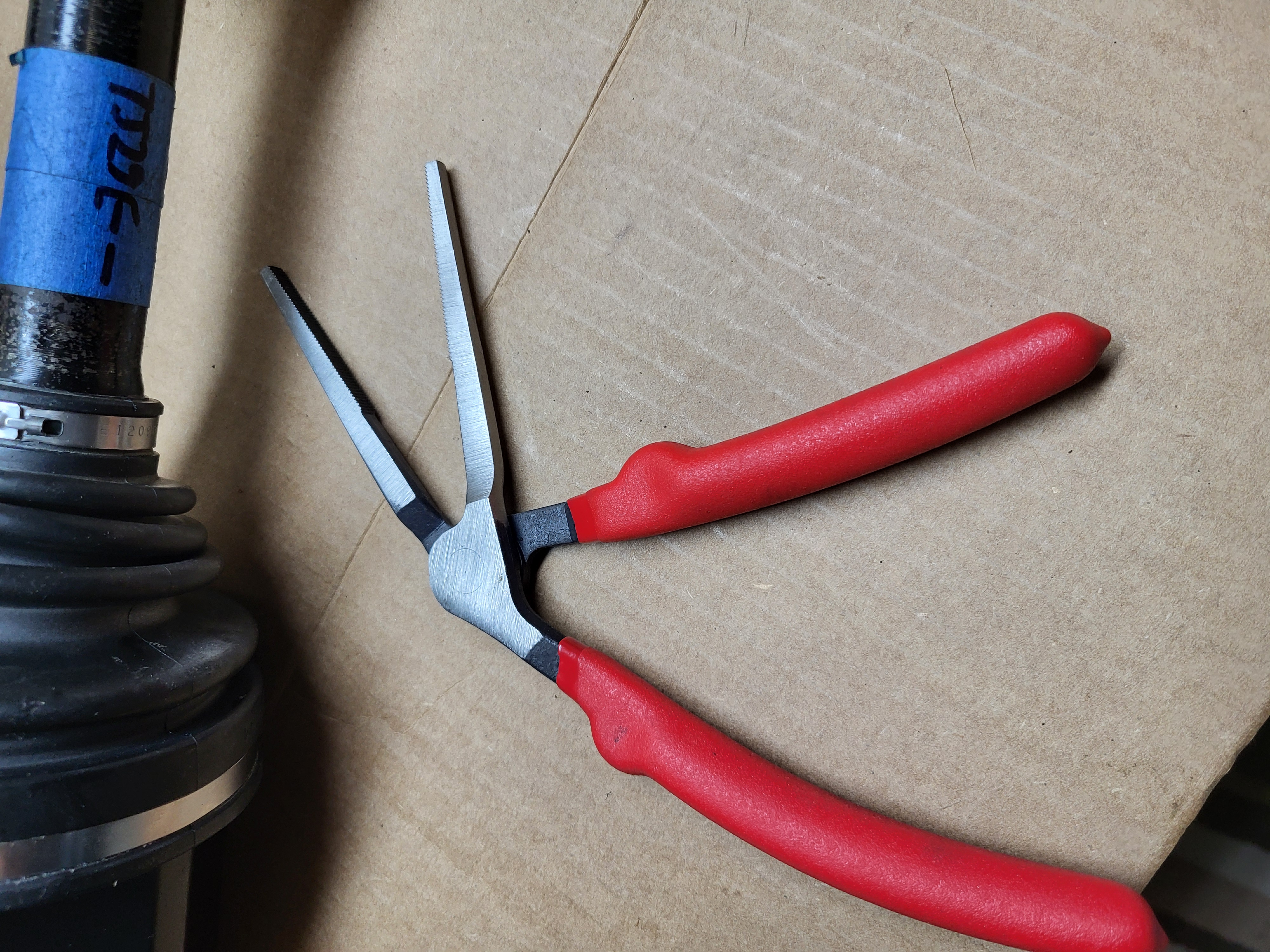
Step 18: Secure the boot clamps to the outboard boot
There are (4) different boot clamps provided with the boot kit. The two wider ones are for the outboard boot. Slide the boot clamps over the boot and tighten. The large clamp is tightened by folding it over and then securing it in place by closing the two tabs over the top of it. This clamp can take a lot of force to close; a brass punch and hammer may be needed for the last little bit. The small clamp is tightened by crimping the protruding section together. The repair manual uses SST 09521-24010 to perform the crimping, knock-off versions of this tool are pretty inexpensive. Alternatively, CV boot pliers or a Pex crimping tool can be used. The gap between the edges that are crimped together should be 0.8mm (0.031in) or less. When using the SST, hold the body of the tool with a crescent wrench and tighten the tool all the way, then remove the tool and tap down the lock tab with a brass punch.
Step 19: Slide on the small inboard boot clamp and boot
Slide the inboard boot clamp and boot on the axle, position the boot into the groove on the axle. This step needs to be performed before re-installing the tripod and snap ring.
Step 20: Align the tripod and install
If electrical tape was used on the inboard axle splines, remove it, and then align the tripod to the match marks and install onto the axle. The tripod may slide right on. If it does not, use a brass punch tap on the tripod housing near the axle shaft to slide the tripod onto the axle shaft. Do not tap on the rollers. Note that the shallower splines on the interior of the tripod slide on first.
Step 21: Install the snap ring
Using snap-ring pliers, open the snap ring and install it into the groove on the axle.
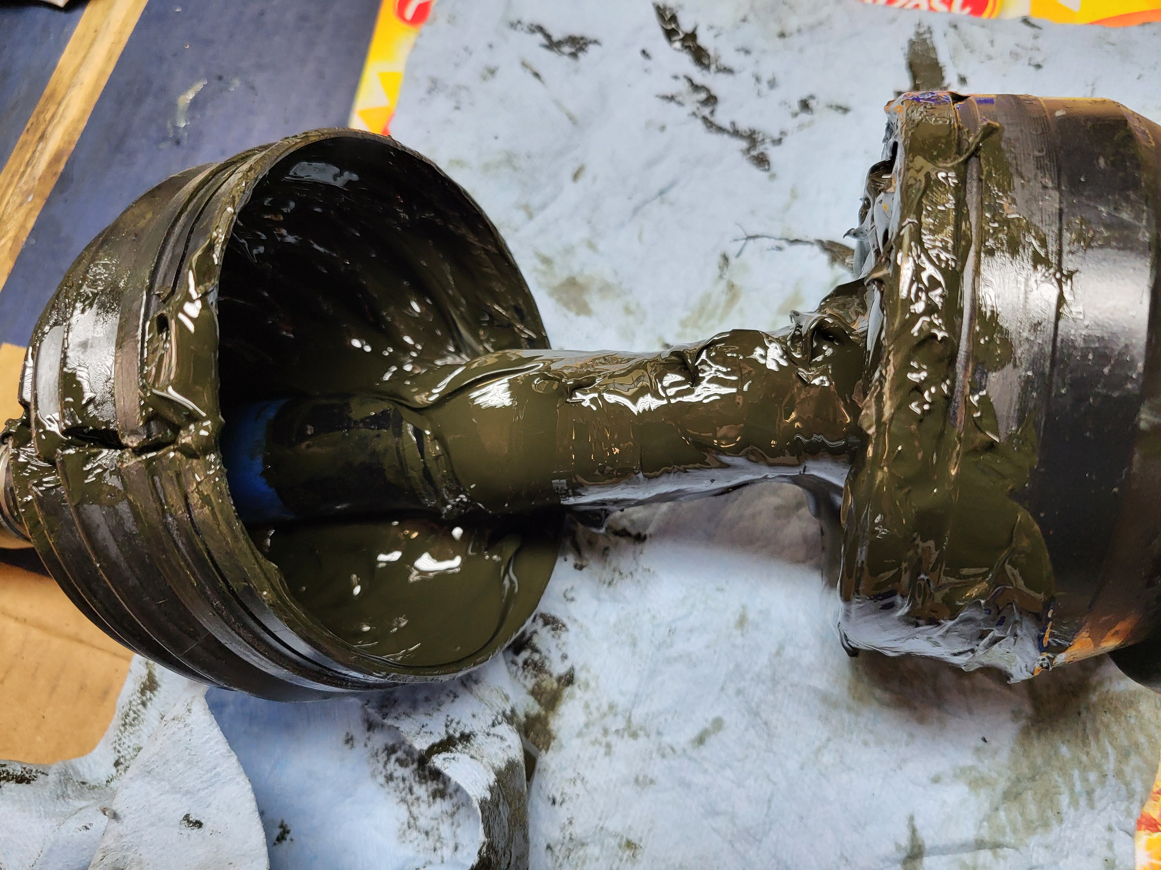
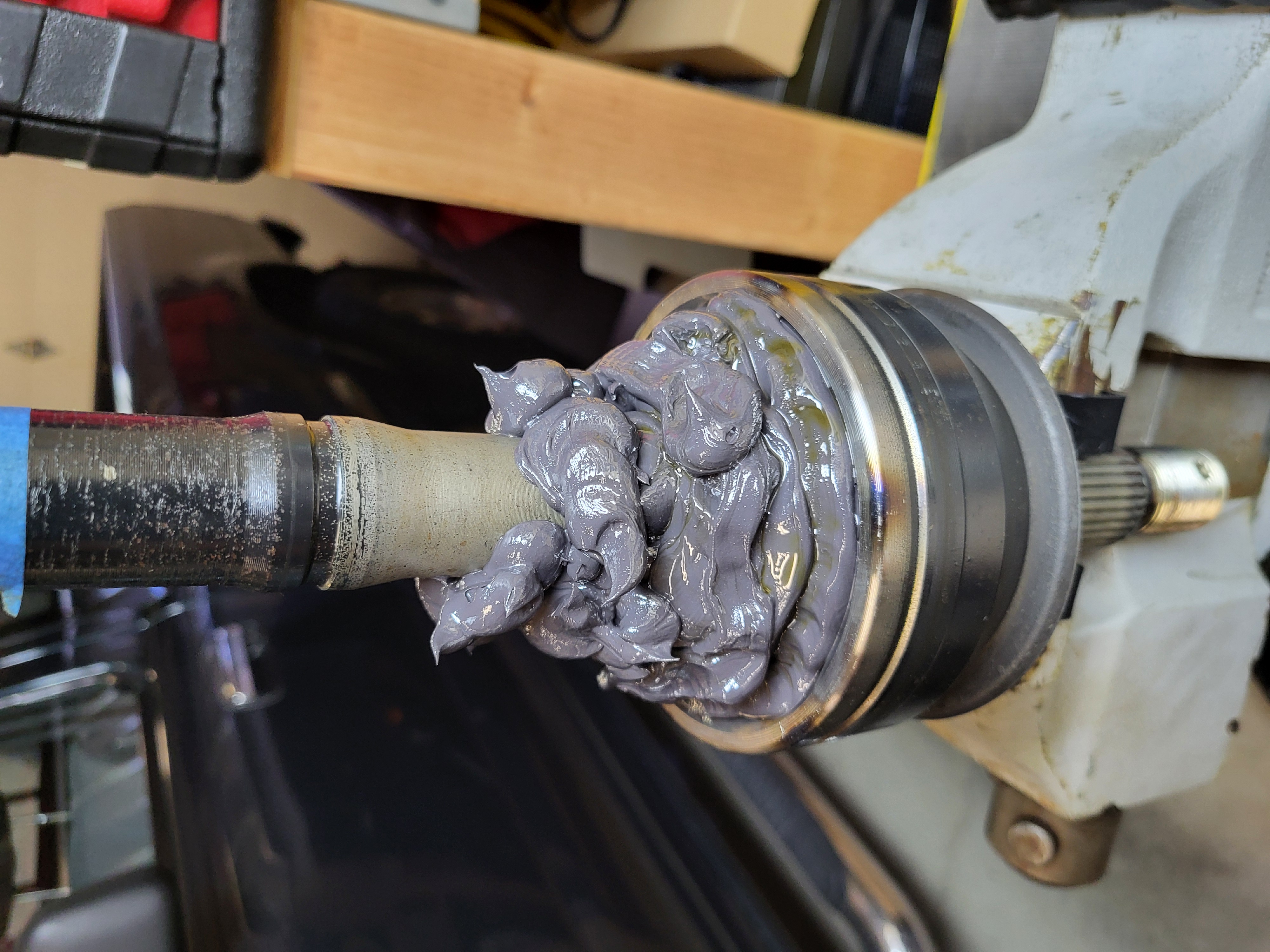
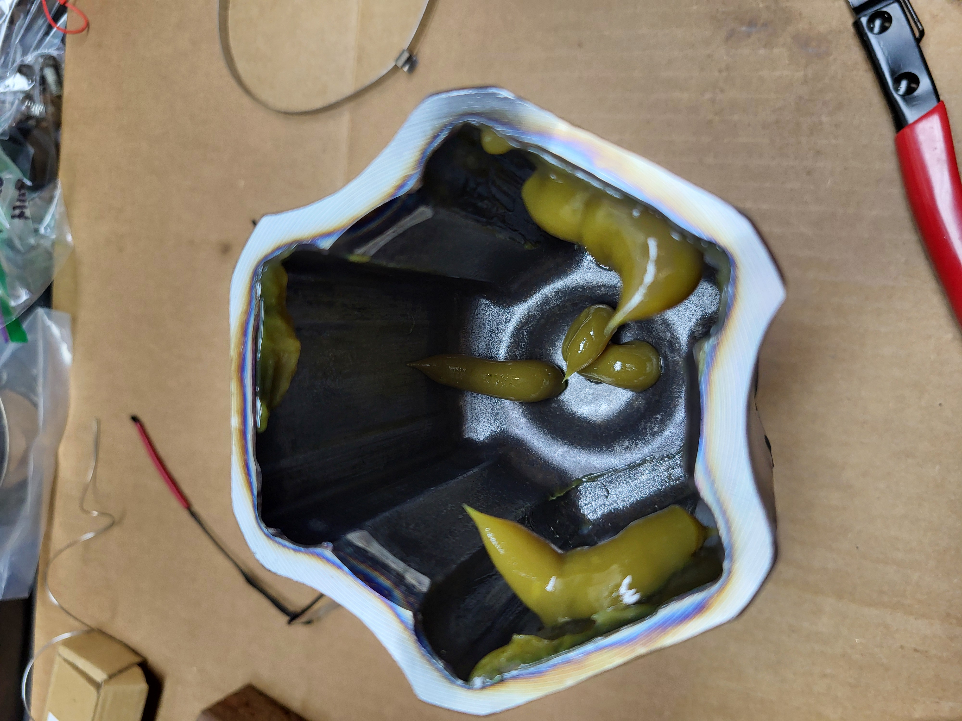
Step 22: Apply grease to the outboard CV joint
The inboard joint uses the tan colored grease in the clear tube that is included with the boot kit. Align the boot with the tripod so the lobes will fit the housing properly. With the axle secured in a vice with the inboard end facing up, fill the boot with the grease and pack the tripod bearings. The housing can be greased as well, where the bearings ride, but it is not necessary.
Step 23: Install the inboard housing
Align the housing match marks with the axle match marks and slide housing over the tripod. Getting all three rollers to slide into the housing at the same time can be difficult, but eventually it will slide on. Snap the boot into the recess on the housing.
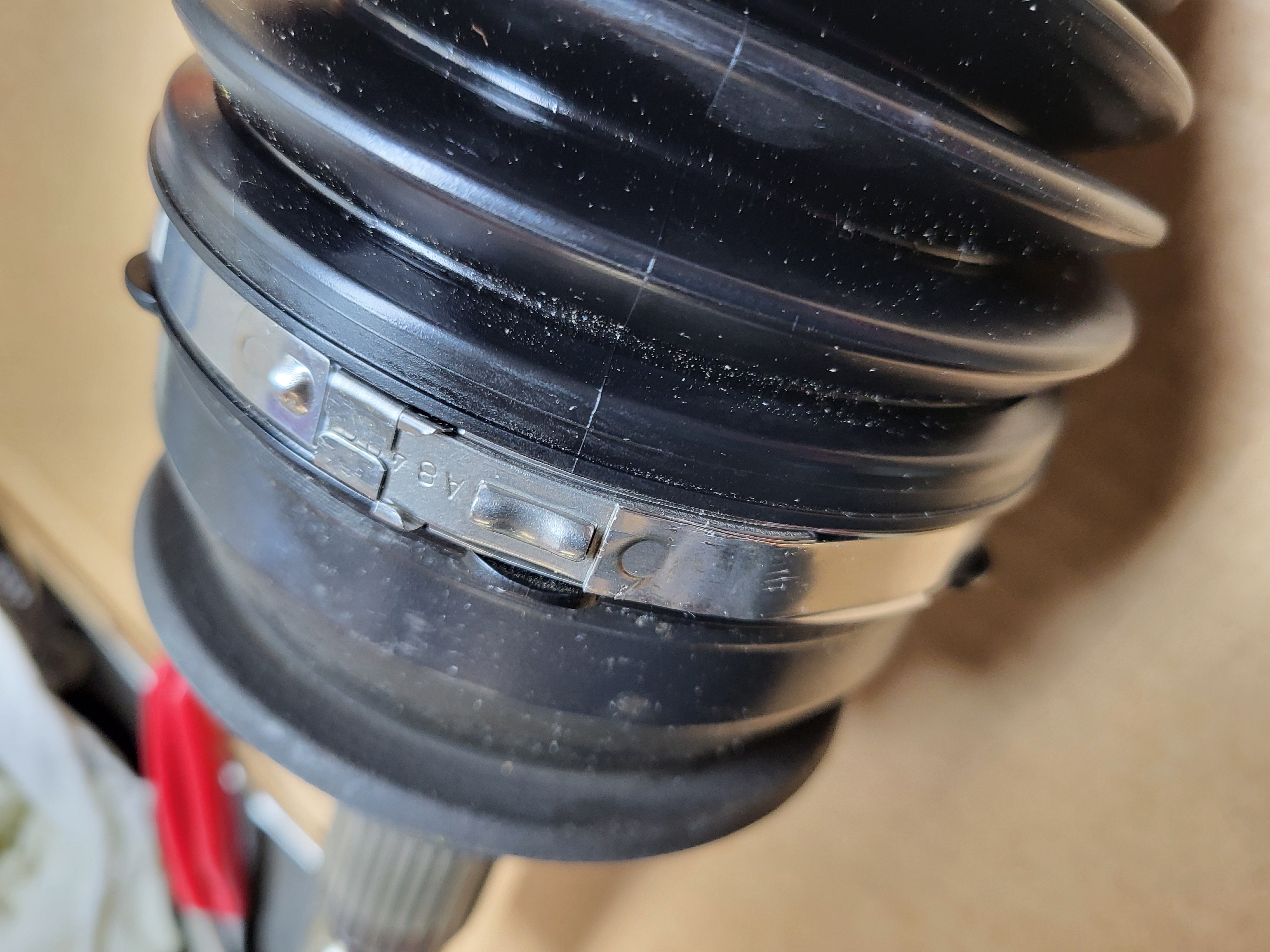
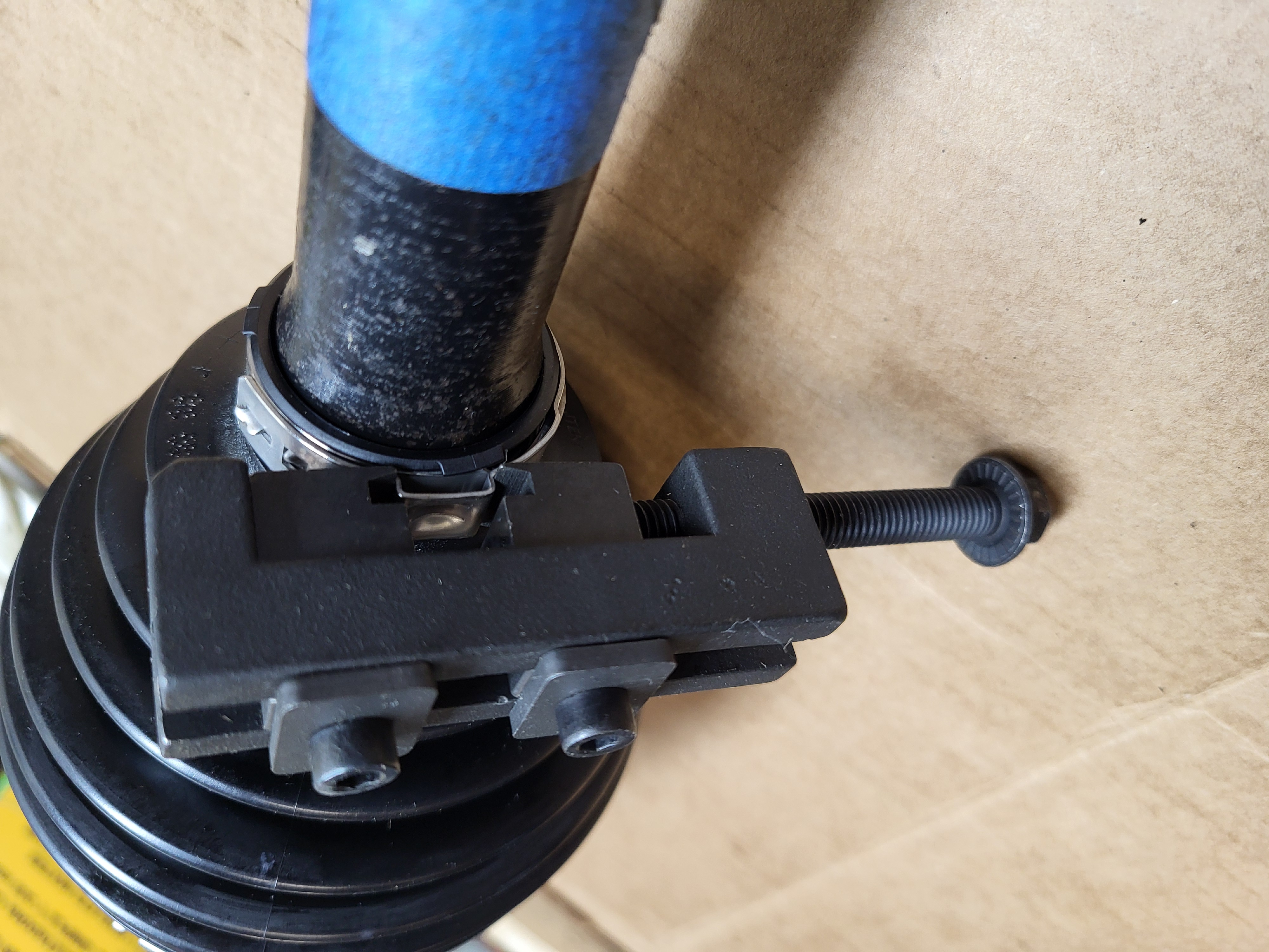
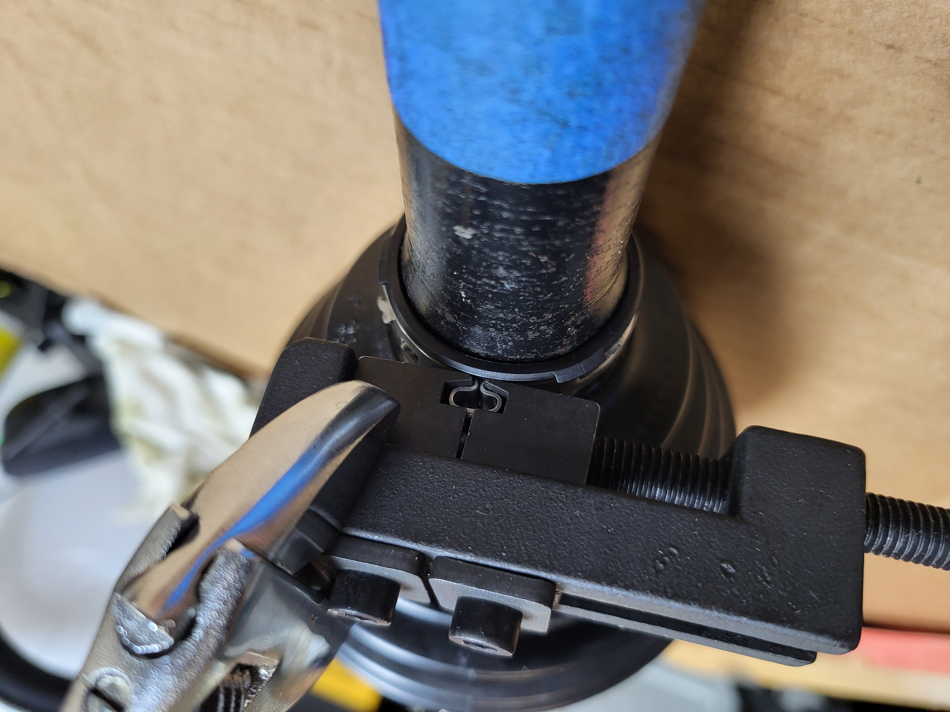
Step 24: Secure the boot clamps to the inboard boot
There are (4) different boot clamps provided with the boot kit; the two thinner ones are for the outboard boot. Slide the boot clamps over the boot and tighten. The large clamp is tightened by folding it over and then securing it in place by closing the two tabs over the top of it. This clamp springs open if not held down by the tabs, be prepared to hammer the tabs while holding the clamp closed. The small clamp is tightened by using (kiwi) pliers and closing it until the inner retaining tabs fit into the outer holes. Once it is positioned properly, use a brass punch and tap down the outer tab to keep the clamp closed.
Step 25: Clean up
Clean any grease that may have gotten onto the exterior components and remove the match mark tape from the axle.
Differential and Steering Knuckle Seal Replacement
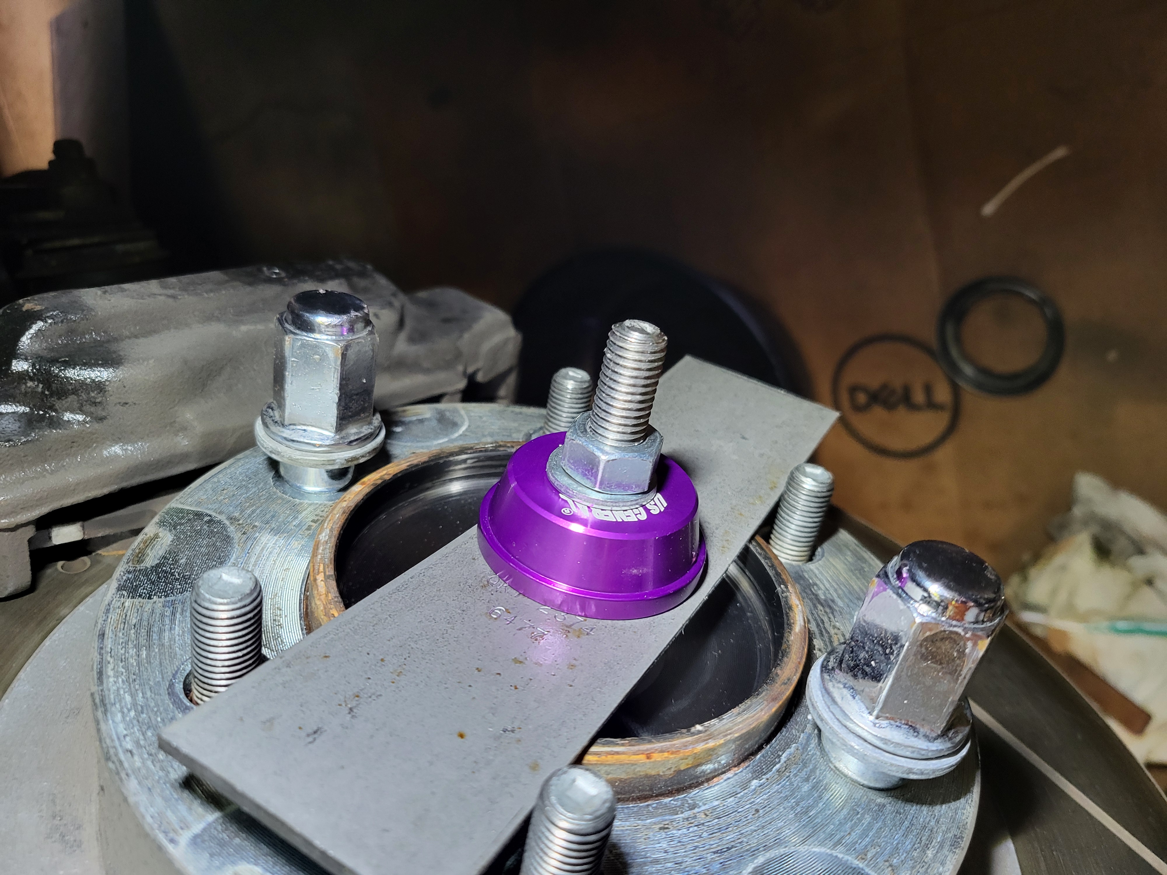
Step 1: Remove the steering knuckle seal
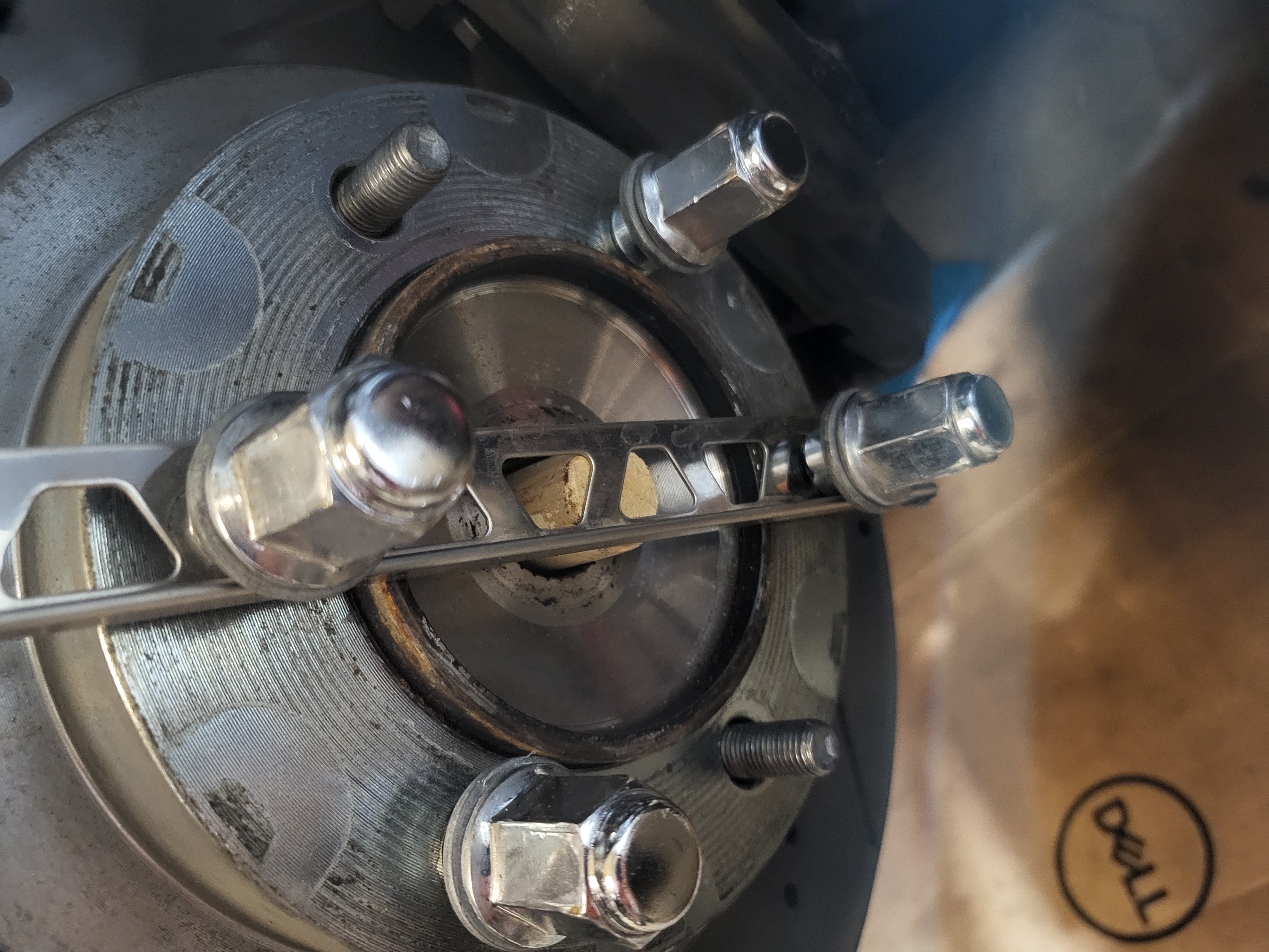
The knuckle seal can be removed many different ways, however there is a novel setup that works with a simple seal puller without putting force onto the bearing surface:
1) Attach a strap of metal or strong wood to the outside of the hub and use the lug nuts to secure it.
2) Cut a large wooden dowel or broom handle that can fit through the inside of the hub. The dowel will contact the outer strap and protrude approximately .25" (6-7mm) from the inside surface of the bearing (3.65" OAL).
3) Hook the seal puller under the seal and then leverage the puller against the wooden dowel to pop the seal out. Note: the knuckle has a ledge that can accidentally be hooked if the puller reaches too far in.
Step 2: Clean the steering knuckle seal surface
Prior to installing the new steering knuckle seal, clean the seating surfaces of the knuckle to remove rust and debris. To prevent contamination to the sealed bearing, tin foil can be pushed into the knuckle to protect it. Cleaning can be accomplished with Scotch-Brite pads and shop rags saturated with solvent.
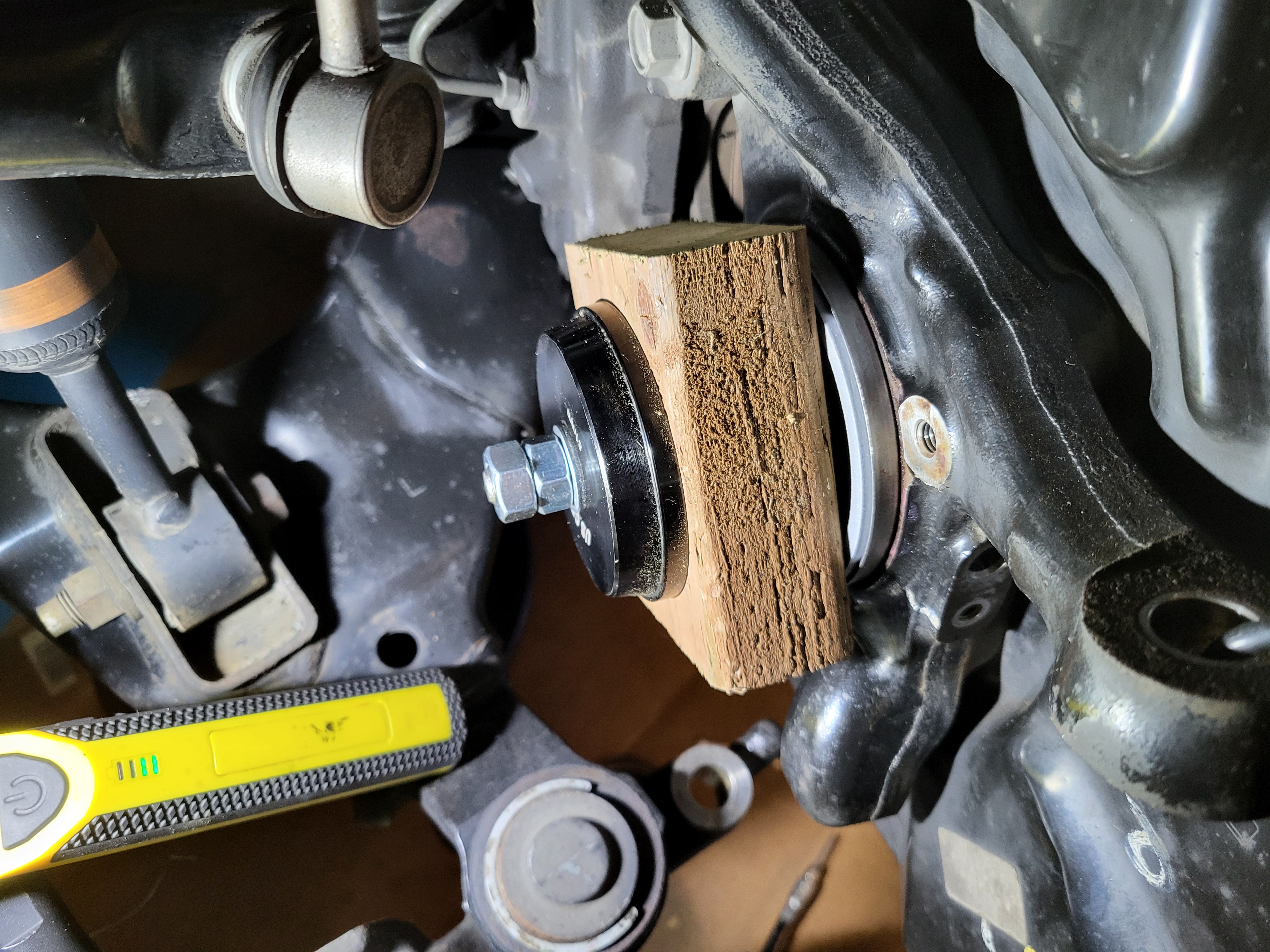
Step 3: Install the steering knuckle seal
As with removal, the knuckle seal can be installed many different ways, however the method shown in the "How to Change Wheel Hub Bearings on GX470, 4Runner, FJ Cruiser Tacoma 4x4" video is a good way to do it without damaging the seal. The process is outlined below:
1) Apply multipurpose grease to the seating surface of the seal and knuckle.
2) Start the seal into the knuckle keeping it even all the way around.
3) Prepare the setup that includes a thread rod, nuts, a metal support, and a chunk of wood so that it is tightened against the seal. The setup in the picture shows a M12x250mm threaded rod, nut, washer, seal driver, and an edger blade on the outside, then a 3D printed support fitting inside the edge of the seal (solid PLA with an OD of 98mm, ID of 89mm, and a thickness of 9mm), a 2x4 with a hole drilled through the center, a seal driver, washer, and a couple of nuts. Note: make sure the 2x4 is free of dust, otherwise it can get into the knuckle seal grease.
4) With the setup in position, start to tighten the outside nut to draw the seal into the knuckle, monitor the seal as it is being drawn in to ensure it is going in straight'ish. If it appears to be uneven, some taps on high side of the 2x4 may straighten it out.
5) Once the seal is fully seated, remove the setup and inspect that everything looks correct. Check that it is seated by using a feeler gauge around the outside edge. If the feeler gauge slips into a gap, a few taps in that area should close the gap.
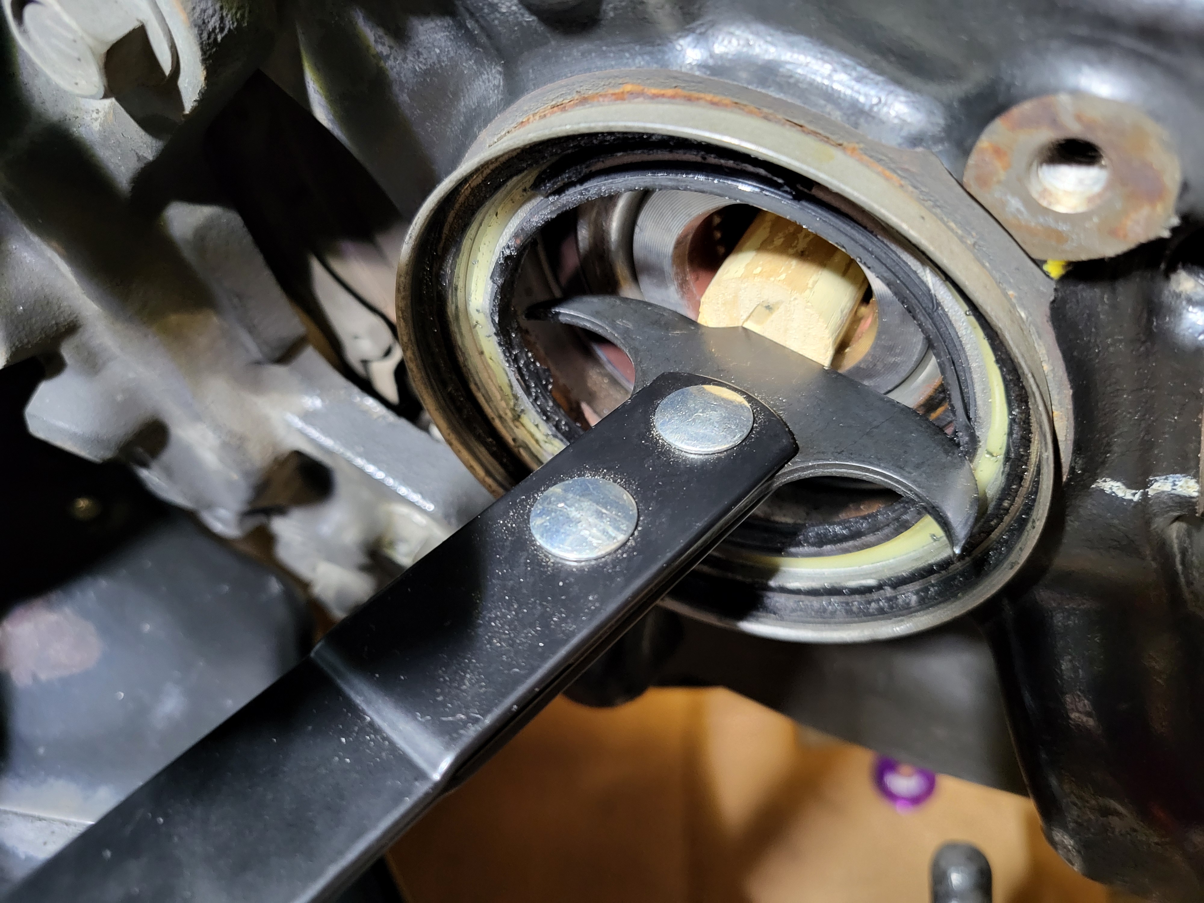
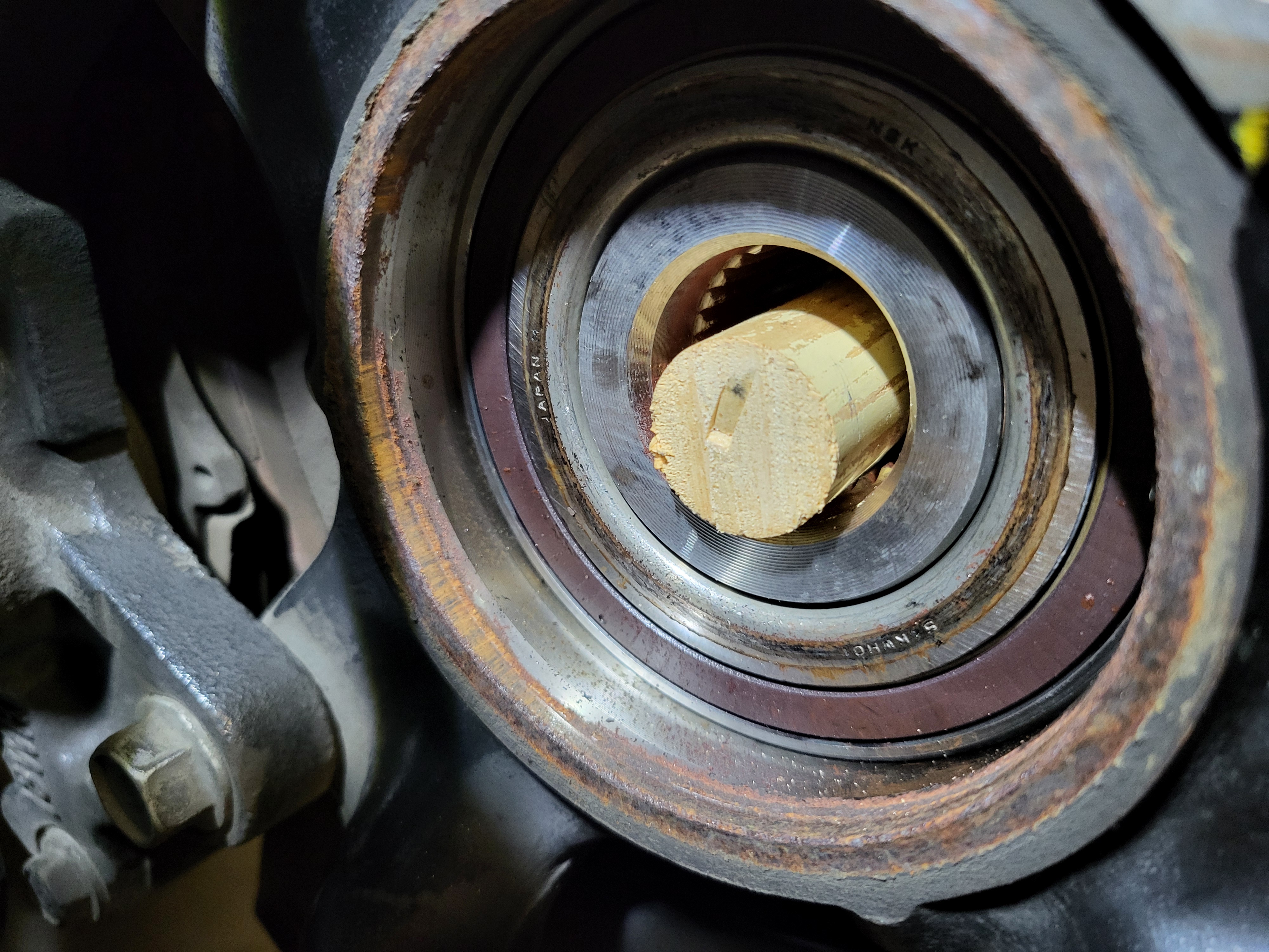
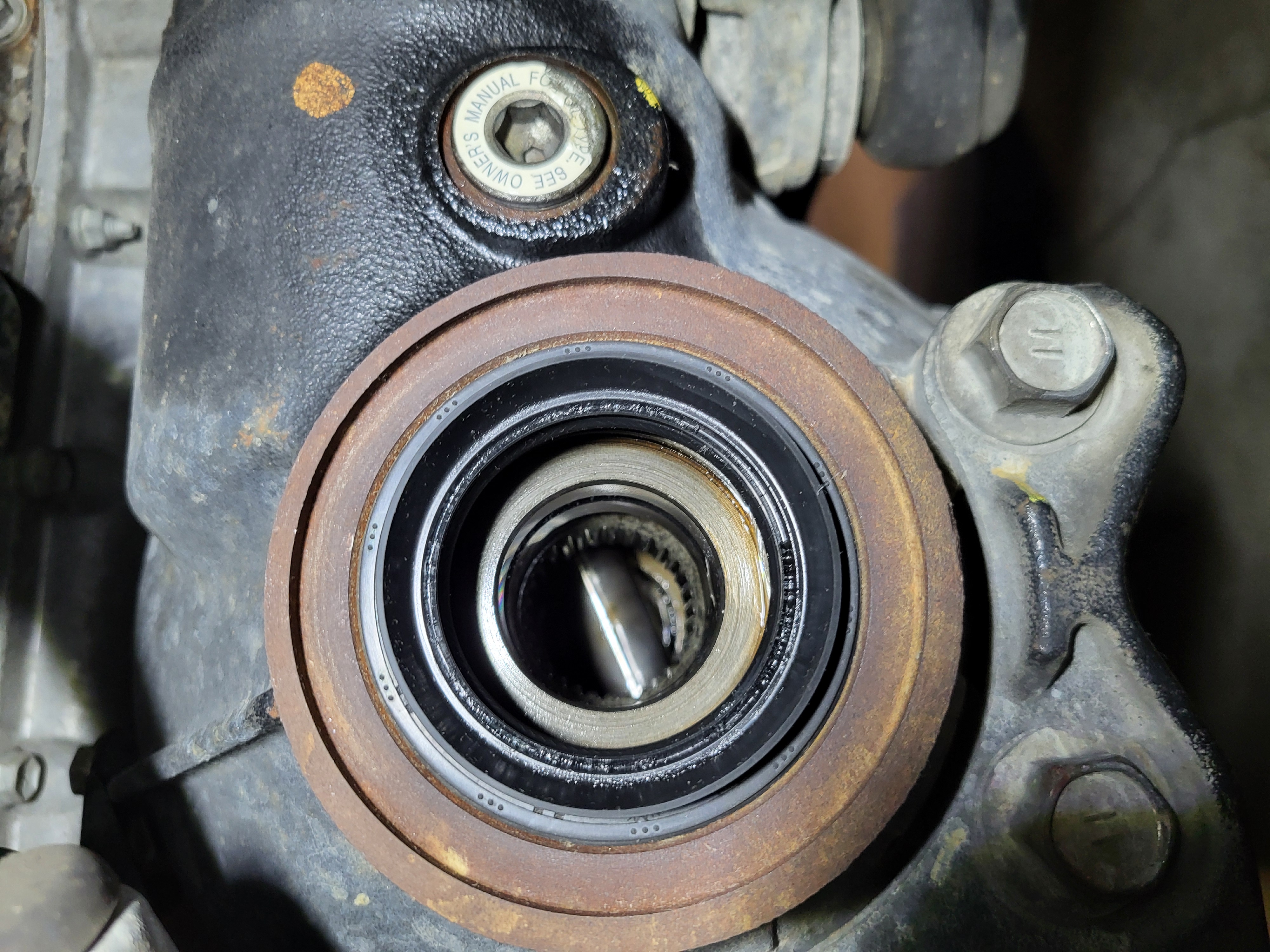
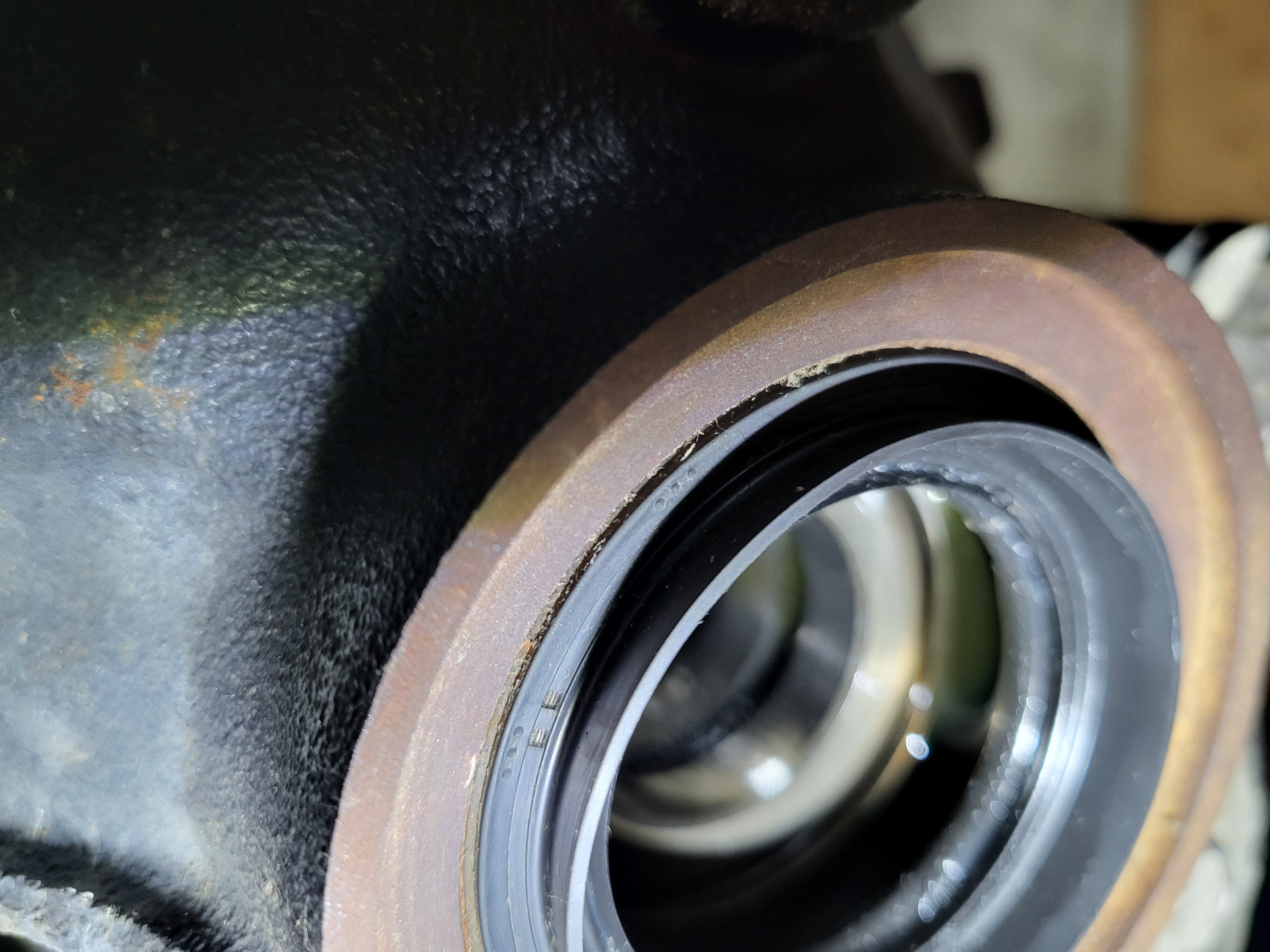
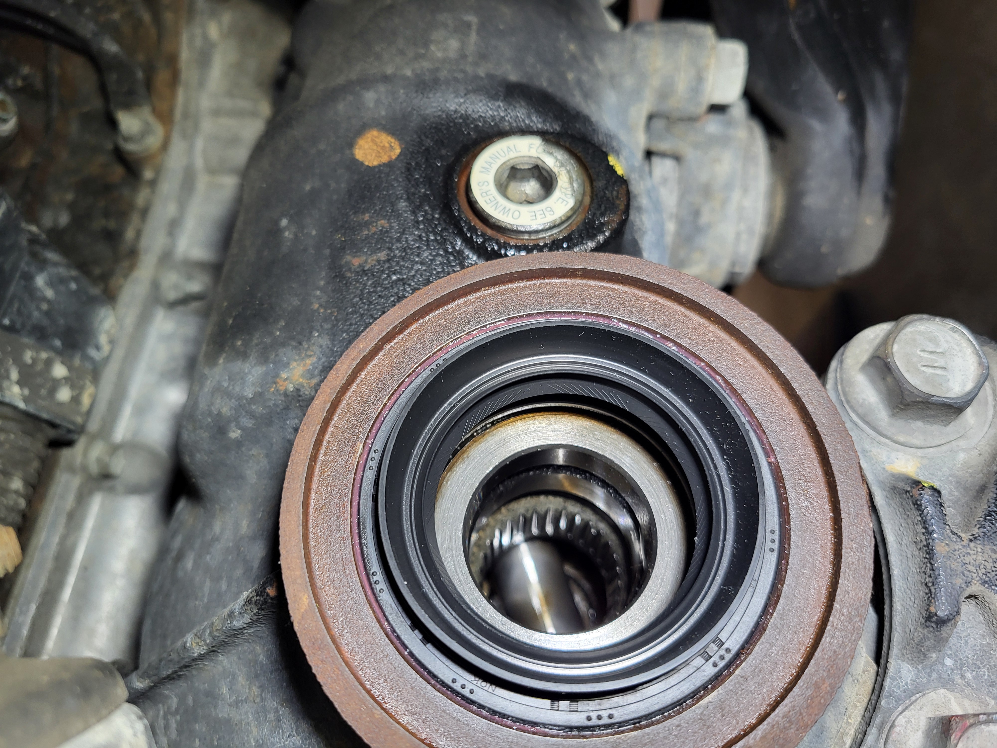
Step 4: Remove the front differential seal
The differential seal can also be removed many different ways. The simplest is probably just a seal puller leveraged against the differential housing with a thin barrier to protect the leverage point on the housing. Check how far the seal puller should be inserted by checking it to the new seal; this should prevent accidentally scratching the sealing surface. Before removing the seal note its depth in the differential.
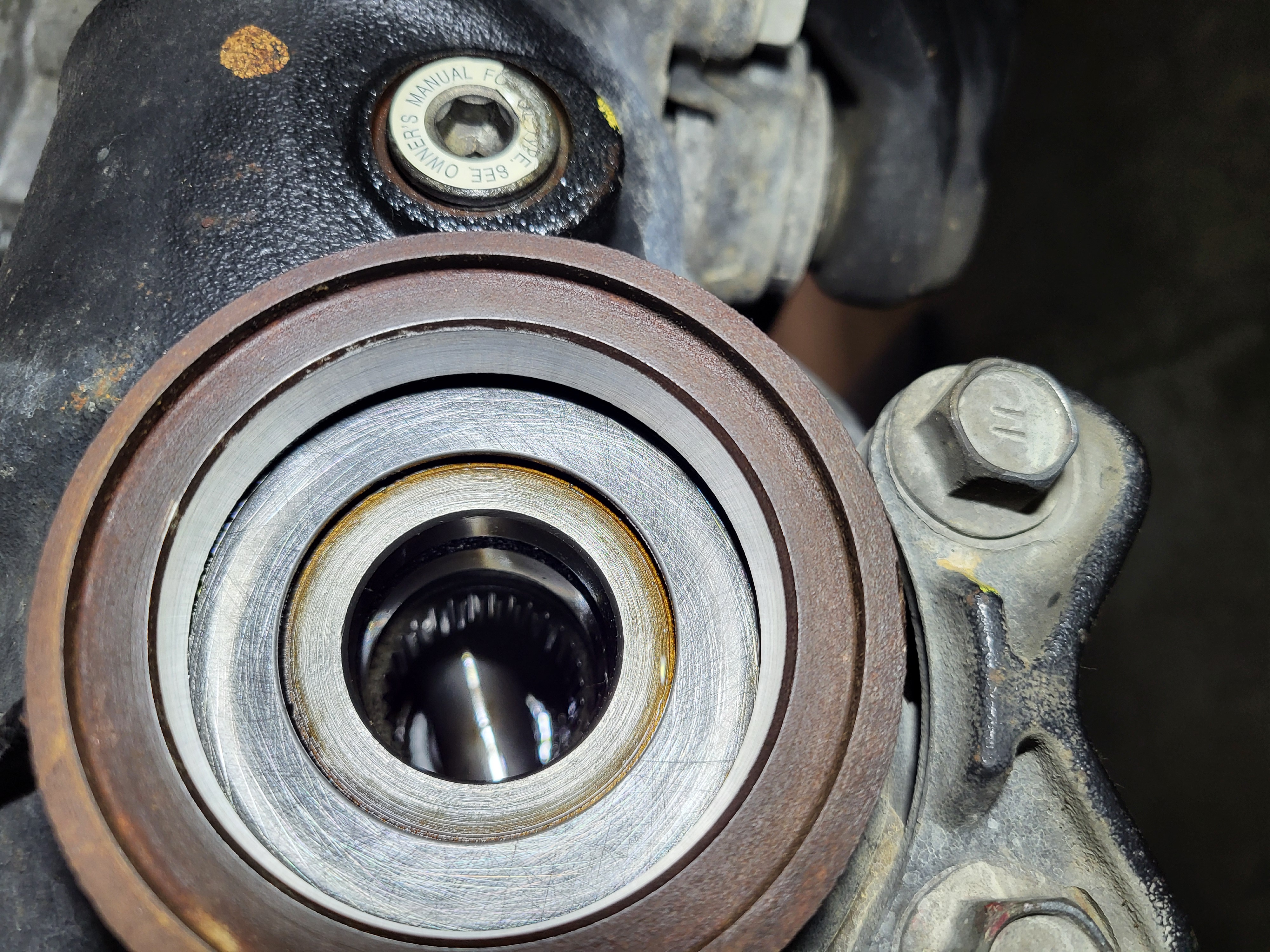
Step 5: Clean the differential seal surface
Prior to installing the new differential seal, clean the seating surfaces of the differential to remove rust and debris, if any. This area is generally pretty clean, and only the small chamfer may need to have some rust knocked down. To prevent contamination from going into the differential, use a small rag or some tin foil to block the hole. Cleaning can be accomplished with Scotch-Brite pads and shop rags saturated with solvent.
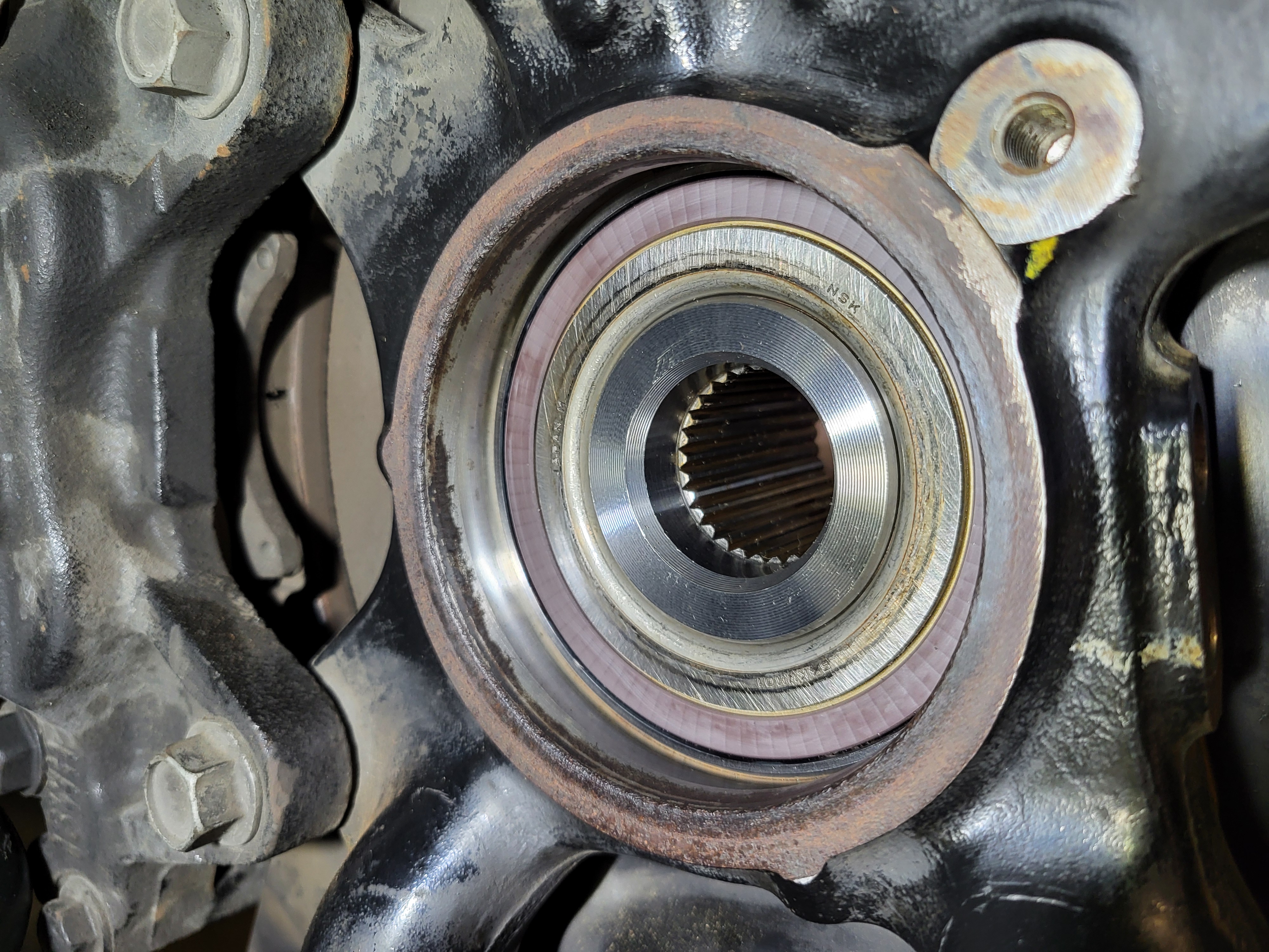
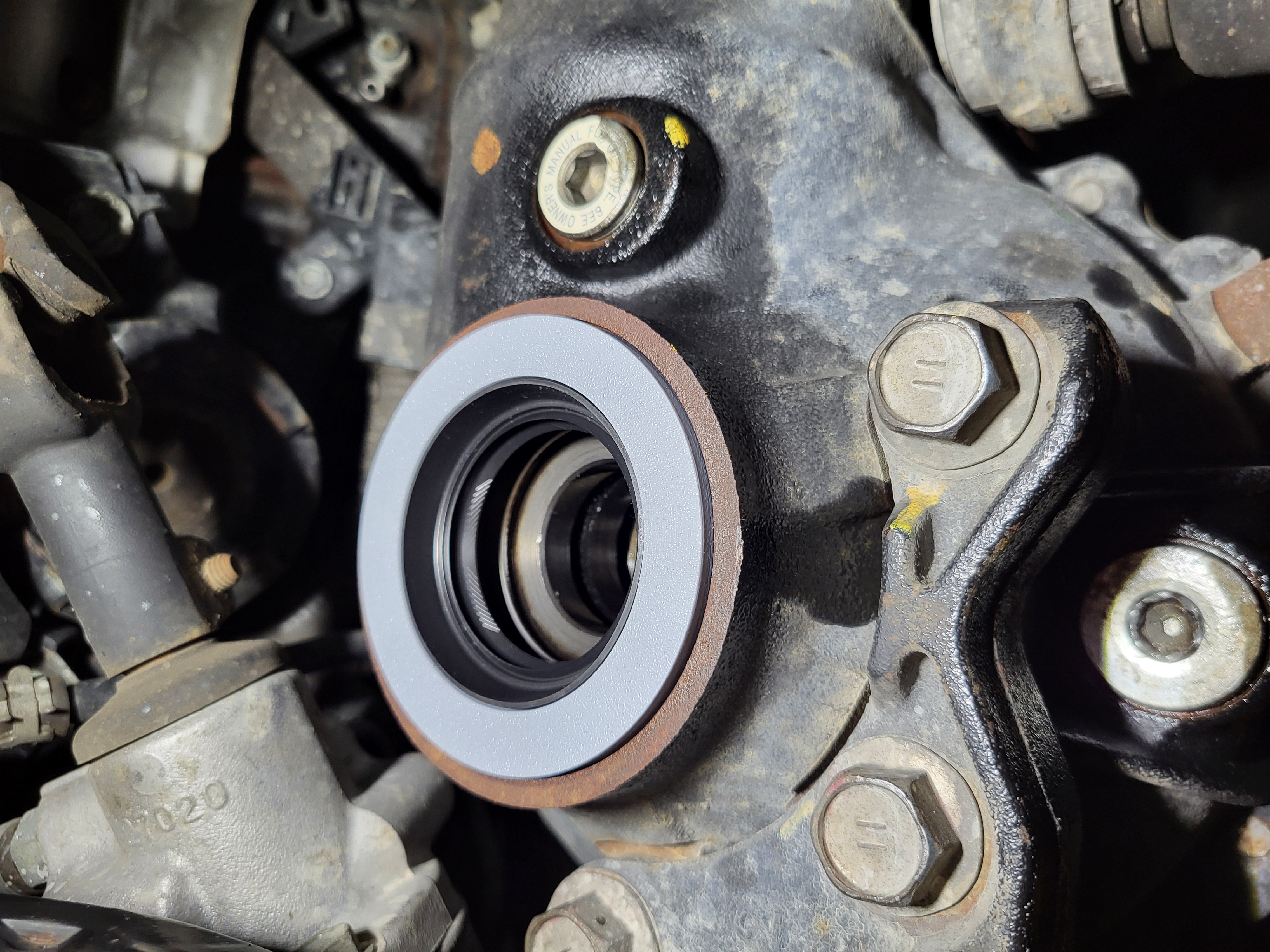
Step 6: Install the differential seal surface
The differential seal has a protruding lip that makes it difficult to drive into place. There are some specialty seal drivers that accommodate this protrusion, but a properly sized piece of pipe can also be used. In the image below a 3D printed ring was used (solid PLA with an OD 83mm, ID of 60.5mm, thickness 6.25, with small ledge that engages just the seal OD 69mm, ID 60.5, thickness 0.25mm). The process used is outlined below:
1) Place the 3D printed ring around the protruding lip of the seal.
2) Apply a thin coat of multipurpose grease on the seating surface of the seal and the differential.
3) Evenly start the seal in the differential.
4) Using a seal driver against the 3D printer ring, tap the seal into place, monitoring the straightness and adjust the tapping area to keep it going in straight. The seal is fully seated when the inner surface of the seal is even with the inner surface of the housing, and the outer protruding lip is about 1.75mm (.069") from the outer surface of the housing. The protrusion can be verified with a flat edge across the outer housing surface and feeler gauges.
CV Axle Installation
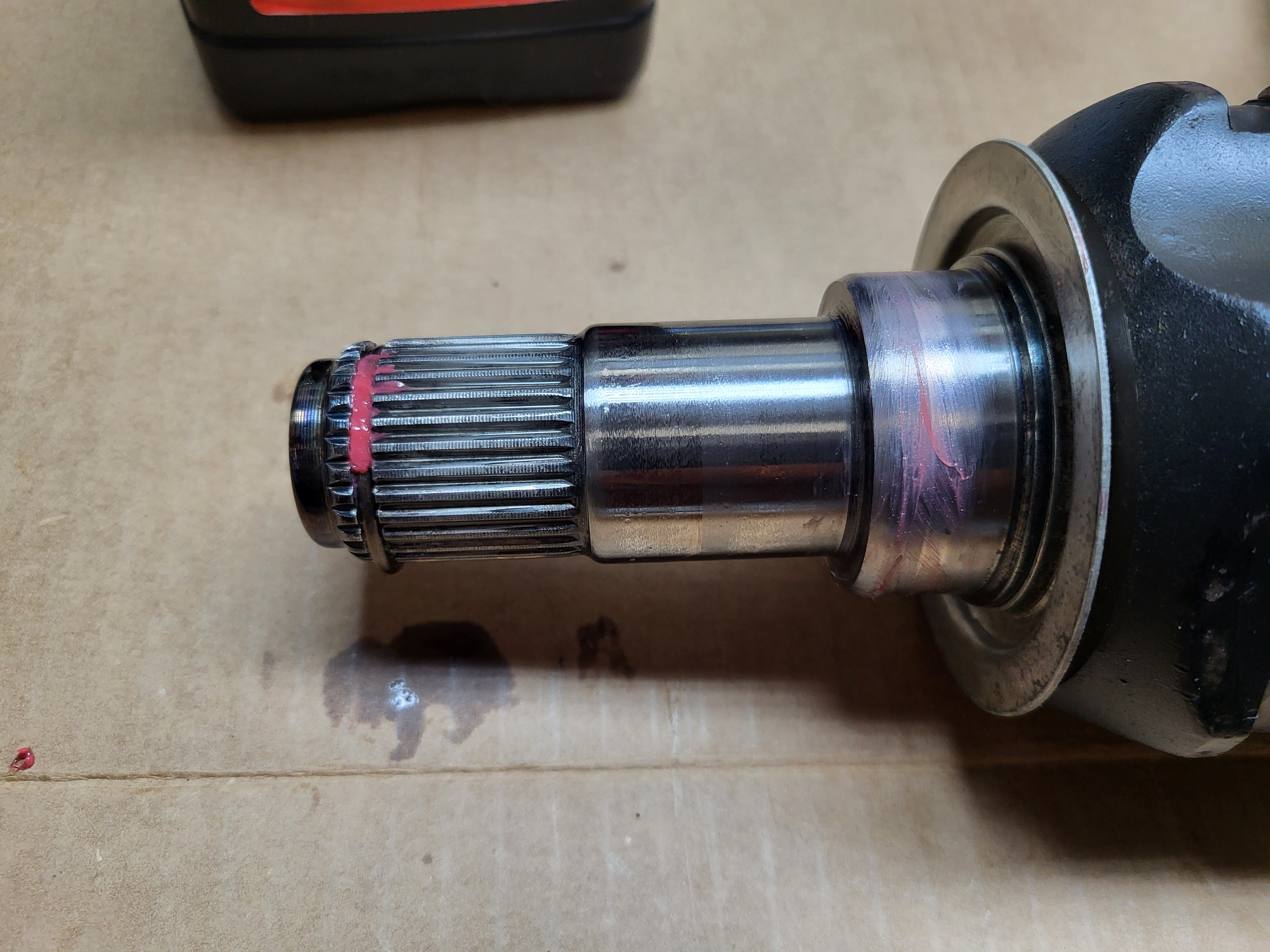
Step 1: Coat the inboard splines with gear oil
The repair manual states ATF, but gear oil would seem to be more appropriate going into the differential.
Step 2: Coat the seal and the axle with multipurpose grease
Lightly coat the seal and the thick part of the inboard axle that the seal rides on with multipurpose grease will help the axle slide into the seal when it is installed.
Step 3: Orientate the inboard C-clip with the opening down
The C-clip should be orientated with the opening down when it is being installed. To prevent gravity from rotating the clip up, add a little bit of multipurpose grease to the axle groove.
Step 4: Install the CV axle into the differential
With the C-clip up, align the axle splines with the differential splines and push the axle into the differential, it will go in just a little bit when the splines are aligned. Then, if you're lucky, the axle can be held completely straight and popped into the differential with a quick push from the outside. If this fails to work, use the small notches on the inboard axle housing to tap the axle into the differential. The axle is all the way in when the inboard dust shield aligns with the outside surface of the differential and there is a little bit of in-and-out play on the axle, indicating that the C-clip is preventing the axle from coming out.
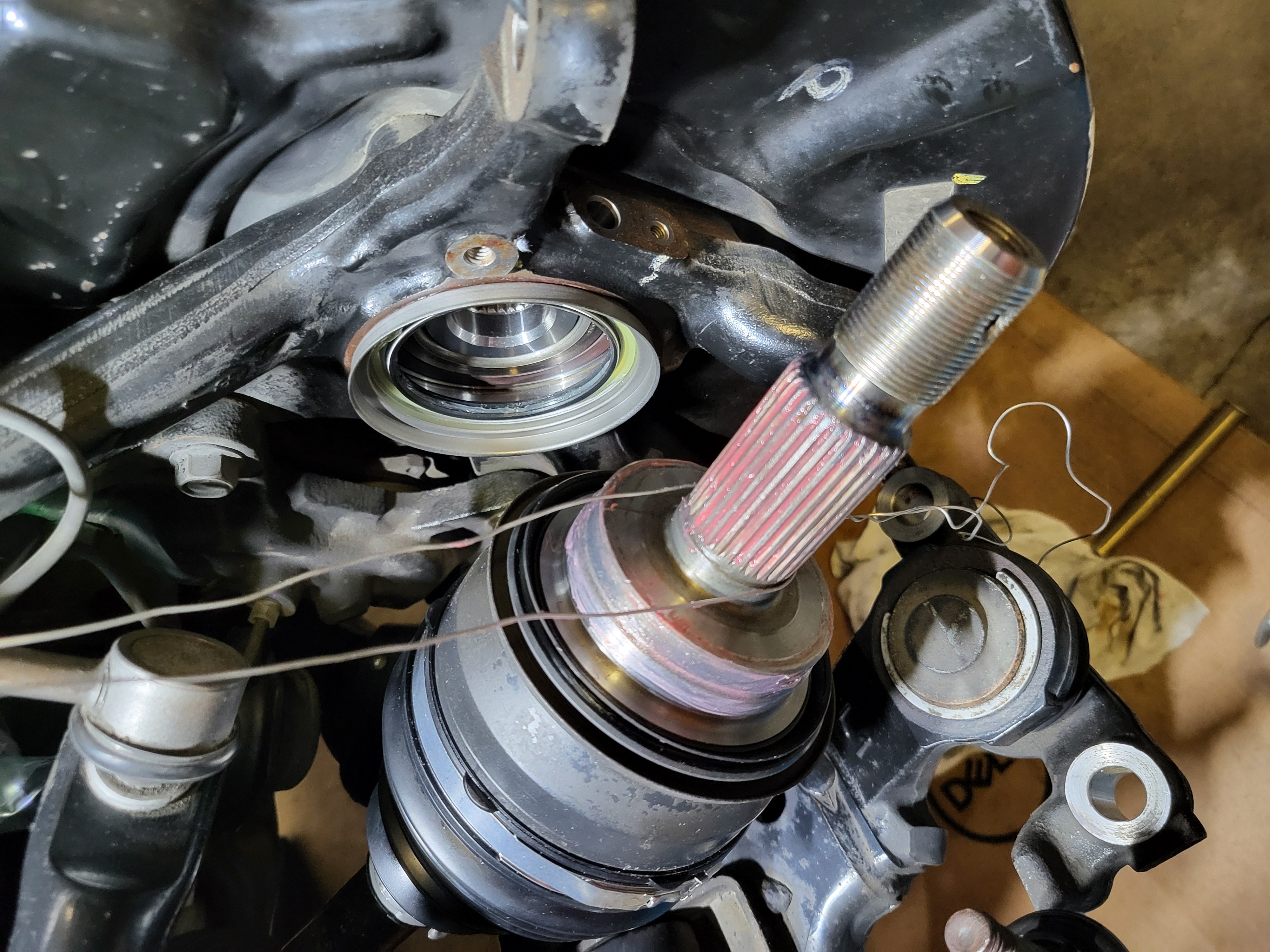
Step 5: Apply multipurpose grease to outboard splines and knuckle seal
Apply multipurpose grease to the splines in the bearing or the splines on the axle or both. Also apply grease to the axle where the knuckle seal will ride.
Step 6: Align the axle and knuckle and slide the axle through
Align the splines in the axle with the splines in the knuckle and slide the axle through. If the axle does not go completely through it can be drawn in with the axle nut.
Step 7: Re-attach the front suspension lower arm
Using a floor jack, lift the lower arm to align with the holes in the knuckle. Install the two (19mm) bolts and tighten. Final torque will be applied after the tie rod is attached.
Step 8: Re-attach the tie rod and install cotter pin
Locate the tie rod end on to the steering knuckle and install the 19mm nut, torque to 67ft-lb. Install a new cotter pin: if the cotter holes do not align with the nut, tighten the nut further (up to 60 degrees) to achieve alignment. If the bolt shaft spins during nut installation, apply some force using a jack to the bottom of the tie rod to keep the shaft from spinning.
Step 9: Torque the front suspension lower arm bolts
With the tie rod keeping the knuckle from moving, the final torque of 118ft-lb can be applied to the 19mm lower arm bolts.
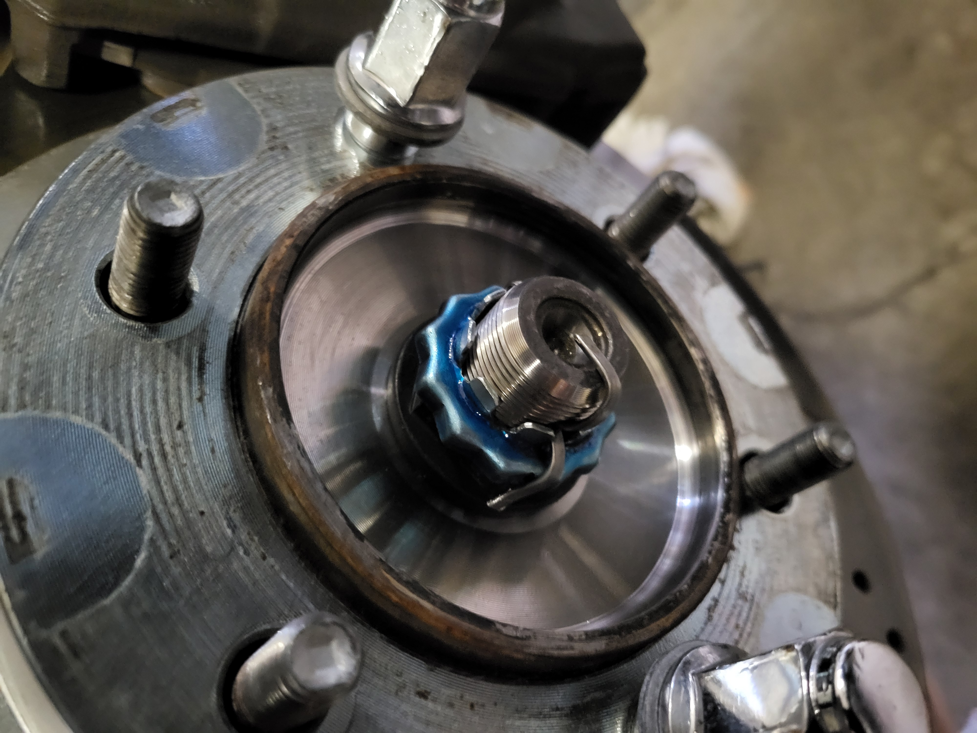
Step 10: Install the axle nut, locking/adjusting cap, and cotter pin
Put the axle nut on the end of the CV shaft (it may already be on if installed to draw the axle through the knuckle). Torque the nut to 173ft/lb. You will need an additional person to apply the brakes or the axle may spin when tightening the nut. It is a good idea to clean the brake rotor of any gunk that may have gotten on it first. Locate the adjusting cap to align with a cotter pin hole, and install a new cotter pin.
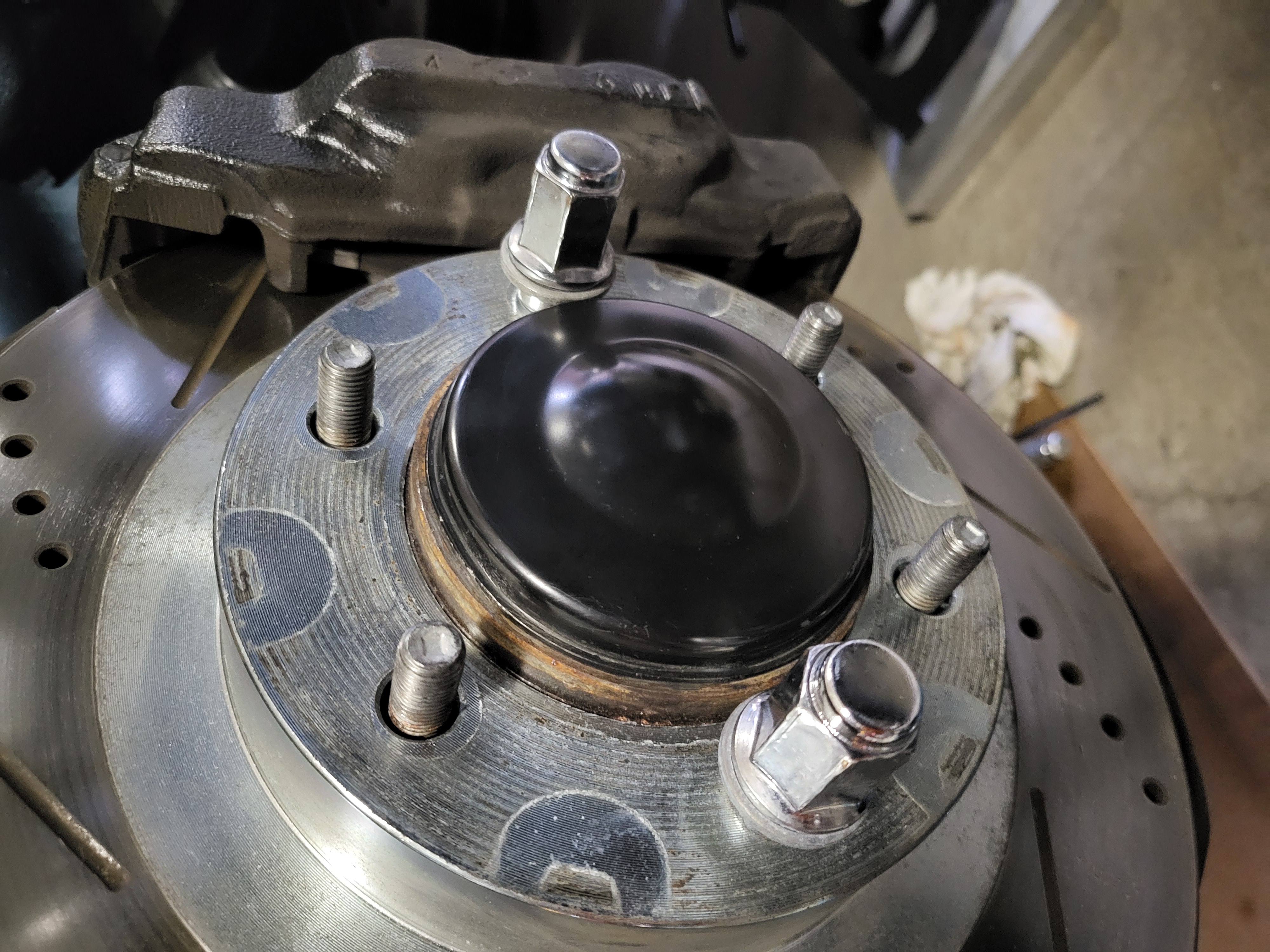
Step 11: Install the axle dust cap
Align the dust cap to the hub and tap on using a plastic or dead-blow hammer.
Step 12: Install the front speed sensor
Install the speed sensor mounting bracket with the 12mm bolt and torque to 10ft-lbs. Then clean the speed sensor and apply a little di-electric grease to the O-ring. Insert the speed sensor into the knuckle and tighten the 5mm internal hex bolt to 73in-lb.
Step 13: Install the front wheel
Remove the lug nuts that were securing the rotor in place, then install the wheel. Tighten the lug nuts in a star pattern to secure the wheel ((5) 21mm nuts, (1) keyed nut). The final torque will be performed with the wheel on the ground.
Step 14: Lower the vehicle
Remove the jack stands and lower the vehicle to the ground.
Step 15: Torque the wheel lug nuts
Torque the lug nuts in a star pattern to 83ft-lb.
Step 16: Level the vehicle
If the vehicle is not level, jack it up as required to level it out. This is necessary to properly fill the front differential.
Step 17: Drain the front differential
Remove the front differential drain bolt and drain any remaining gear oil from the differential.
Step 18: Fill the front differential
Reinstall the drain bolt with a new washer. This is a good time to replace the 10mm internal hex drain bolt with a 14mm drain bolt. Torque to 36ft-lb (the Repair Manual states 48ft-lb), but because this bolt is being installed with oil on the housing threads the torque should be reduced. Remove the fill bolt and fill the differential until fluid comes out of the fill hole, approximately 1.45 liters or 1.53 quarts. Reinstall the drain bolt with a new crush washer (flat side against the bolt), this is a good time to replace the 10mm internal hex fill bolt with a 14mm fill bolt. Torque to 22ft-lb (the Repair Manual states 29ft-lb), but because this bolt is being installed with oil on the housing threads the torque should be reduce.
Step 19: Reinstall the skid plate
Reinstall the skid plate using (4) 12mm bolts with 3" extension. The Repair Manual shows the "Engine Under Cover Sub-Assembly" being torqued to 21ft-lb - this seems excessive, use 10ft-lb.
Step 20: Test drive
Test drive the vehicle, listen for any abnormalities, and then check for leaks.